HP dc73 Service Reference Guide - HP Compaq dc7800 Business PC - Page 167
Backwall, Unlocking the, Smart Cover Lock, on Preparation for Disassembly, Computer Access Panel
 |
View all HP dc73 manuals
Add to My Manuals
Save this manual to your list of manuals |
Page 167 highlights
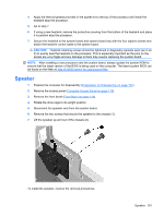
CAUTION: Before reinstalling the heatsink you must clean the top of the processor and the bottom of the heatsink with an alcohol pad supplied in the spares kit. After the alcohol has evaporated, apply thermal grease to the top of the processor from the syringe supplied in the spares kit. CAUTION: When reconnecting the cables it is important that they be positioned so they do not interfere with the rotation of the drive cage or power supply. Backwall 1. If you have locked the Smart Cover Lock, use Computer Setup to unlock the lock (Unlocking the Smart Cover Lock on page 108) 2. Prepare the computer for disassembly (Preparation for Disassembly on page 107). 3. Remove the access panel (Computer Access Panel on page 113). 4. Rotate the drive cage to its upright position. 5. Remove the power supply (Power Supply on page 152). 6. If necessary, remove the SmartCover lock from the backwall of the chassis using the special security wrench and disconnect its cable from the system board (Unlocking the Smart Cover Lock on page 108). 7. Remove the system board (System Board on page 153). Backwall 155
-
 1
1 -
2
-
3
-
4
-
5
-
6
-
7
-
8
-
9
-
10
-
11
-
12
-
13
-
14
-
15
-
16
-
17
-
18
-
19
-
20
-
21
-
22
-
23
-
24
-
25
-
26
-
27
-
28
-
29
-
30
-
31
-
32
-
33
-
34
-
35
-
36
-
37
-
38
-
39
-
40
-
41
-
42
-
43
-
44
-
45
-
46
-
47
-
48
-
49
-
50
-
51
-
52
-
53
-
54
-
55
-
56
-
57
-
58
-
59
-
60
-
61
-
62
-
63
-
64
-
65
-
66
-
67
-
68
-
69
-
70
-
71
-
72
-
73
-
74
-
75
-
76
-
77
-
78
-
79
-
80
-
81
-
82
-
83
-
84
-
85
-
86
-
87
-
88
-
89
-
90
-
91
-
92
-
93
-
94
-
95
-
96
-
97
-
98
-
99
-
100
-
101
-
102
-
103
-
104
-
105
-
106
-
107
-
108
-
109
-
110
-
111
-
112
-
113
-
114
-
115
-
116
-
117
-
118
-
119
-
120
-
121
-
122
-
123
-
124
-
125
-
126
-
127
-
128
-
129
-
130
-
131
-
132
-
133
-
134
-
135
-
136
-
137
-
138
-
139
-
140
-
141
-
142
-
143
-
144
-
145
-
146
-
147
-
148
-
149
-
150
-
151
-
152
-
153
-
154
-
155
-
156
-
157
-
158
-
159
-
160
-
161
-
 162
162 -
 163
163 -
 164
164 -
 165
165 -
 166
166 -
 167
167 -
 168
168 -
 169
169 -
 170
170 -
 171
171 -
 172
172 -
173
-
174
-
175
-
176
-
177
-
178
-
179
-
180
-
181
-
182
-
183
-
184
-
185
-
186
-
187
-
188
-
189
-
190
-
191
-
192
-
193
-
194
-
195
-
196
-
197
-
198
-
199
-
200
-
201
-
202
-
203
-
204
-
205
-
206
-
207
-
208
-
209
-
210
-
211
-
212
-
213
-
214
-
215
-
216
-
217
-
218
-
219
-
220
-
221
-
222
-
223
-
224
-
225
-
226
-
227
-
228
-
229
-
230
-
231
-
232
-
233
-
234
-
235
-
236
-
237
-
238
-
239
-
240
-
241
-
242
-
243
-
244
-
245
-
246
-
247
-
248
-
249
-
250
-
251
-
252
-
253
-
254
-
255
-
256
-
257
-
258
-
259
-
260
-
261
-
262
-
263
-
264
-
265
-
266
-
267
-
268
-
269
-
270
-
271
-
272
-
273
-
274
-
275
-
276
 |
 |
