IBM 7014-T42 User Guide - Page 18
Insert a rack-mounting bolt assembly through each of the leveling feet.
 |
View all IBM 7014-T42 manuals
Add to My Manuals
Save this manual to your list of manuals |
Page 18 highlights
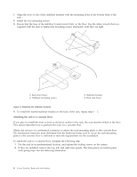
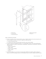
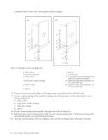
correctly located, remove the lower plastic isolator bushings. Figure 5. Installing ac-power mounting plates 1 Rack chassis 2 Rack-mounting bolt 3 Thin washer 4 Top plastic isolator bushing 5 Thick washer 6 Spacer 7 Jam nut 8 Leveling foot 9 Lower plastic isolator bushing (used only on dc powered systems) ac Typical leveling foot installation for an ac-powered rack dc Typical leveling foot installation for an dc-powered rack 6. Position the two mounting plates in the approximate mounting location under the rack. 7. Create a rack-mounting bolt assembly by adding the following items, in the order listed, to each rack-mounting bolt. a. Thin washer b. Top plastic isolator bushing c. Thick flat washer d. Spacer 8. Insert a rack-mounting bolt assembly through each of the leveling feet. 9. Reposition the rack-mounting plates under the four rack-mounting bolts so that the mounting bolts are centered directly over the threaded bolt holes. 10. Turn the rack-mounting bolts four complete turns into the mounting plate's threaded bolt holes. 6 Power Systems: Racks and rack features
-
 1
1 -
2
-
3
-
4
-
5
-
6
-
7
-
8
-
9
-
10
-
11
-
12
-
 13
13 -
 14
14 -
 15
15 -
 16
16 -
 17
17 -
 18
18 -
 19
19 -
 20
20 -
 21
21 -
 22
22 -
 23
23 -
24
-
25
-
26
-
27
-
28
-
29
-
30
-
31
-
32
-
33
-
34
-
35
-
36
-
37
-
38
-
39
-
40
-
41
-
42
-
43
-
44
-
45
-
46
-
47
-
48
-
49
-
50
-
51
-
52
-
53
-
54
-
55
-
56
-
57
-
58
-
59
-
60
-
61
-
62
-
63
-
64
-
65
-
66
-
67
-
68
-
69
-
70
-
71
-
72
-
73
-
74
 |
 |
