IBM 7014-T42 User Guide - Page 23
are accessible.
 |
View all IBM 7014-T42 manuals
Add to My Manuals
Save this manual to your list of manuals |
Page 23 highlights
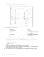
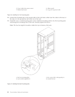
6 Spacer 6. Position the two mounting plates in the approximate mounting location under the rack. 7. Create a rack-mounting bolt assembly by adding the following items, in the order listed, to each rack-mounting bolt. a. Thin washer b. Top plastic isolator bushing c. Thick flat washer d. Spacer 8. Insert a rack-mounting bolt assembly through each of the leveling feet. 9. Reposition the rack-mounting plates under the four rack-mounting bolts so that the mounting bolts are centered directly over the threaded bolt holes. 10. Turn the rack-mounting bolts four complete turns into the mounting plate's threaded bolt holes. 11. Mark the raised-floor panel around the edges of front and rear rack-mounting plates. 12. Mark the plate bolt-down holes that are accessible through the opening in the rear of the rack. 13. Remove the rack-mounting bolt assemblies. 14. If you are installing an ac-powered rack, remove the bottom isolator bushing from each of the leveling feet. 15. Remove the rack-mounting plates from the marked locations. 16. Loosen each of the locking screws on the casters. 17. Move the rack so that it is clear of both areas that were marked on the floor for the rack-mounting plate locations. 18. Reposition the mounting plates within the marked areas. 19. Mark the raised-floor panel at the center of each hole in the rack-mounting plates (including the tapped holes). 20. Remove the two rack-mounting plates from the marked locations on the raised floor panel. 21. Drill two clearance holes on each end of each rack-mounting plate. The drilled holes should be approximately 1-inch deep. This depth will accommodate any rack-mounting bolt extending past the rack-mounting plate when securing the rack to the rack-mounting plate. 22. For each rack-mounting plate, select at least two suitable hole locations. Select the hole locations as close to the threaded hole areas as possible. Be sure the hole locations selected at the back of the rack are accessible. 23. Drill pass-through holes in the raised-floor panel. The pass-through holes allow the anchor bolts to be inserted into the rack-mounting plate and pass through the raised floor panel to the concrete floor. Note: You must use a minimum of two anchor bolts for each rack-mounting plate to securely attach the rack-mounting plate through the raised-floor panel to the concrete floor. Because some of the holes in each rack-mounting plate may align with concrete reinforcement rods imbedded in the concrete, some of the rack-mounting plate holes might not be usable. 24. Transfer the locations of the anchor bolt holes (exclude the clearance holes drilled for the rack-mounting bolts) from the raised-floor panel to the concrete floor directly beneath, and mark the hole locations on the concrete floor. 25. Drill holes in the concrete floor to secure the anchor bolts. 26. Position the raised-floor panel back into position over the anchor bolt holes. 27. Position the front stabilizer bracket within the marked area on the raised-floor panel. 28. Using your anchor bolts, secure the front stabilizer brackets on top of the raised floor and through to the concrete floor. 29. Position the rear stabilizer brackets within the marked area on the raised-floor panel. Racks and rack features 11
-
 1
1 -
2
-
3
-
4
-
5
-
6
-
7
-
8
-
9
-
10
-
11
-
12
-
13
-
14
-
15
-
16
-
17
-
 18
18 -
 19
19 -
 20
20 -
 21
21 -
 22
22 -
 23
23 -
 24
24 -
 25
25 -
 26
26 -
 27
27 -
 28
28 -
29
-
30
-
31
-
32
-
33
-
34
-
35
-
36
-
37
-
38
-
39
-
40
-
41
-
42
-
43
-
44
-
45
-
46
-
47
-
48
-
49
-
50
-
51
-
52
-
53
-
54
-
55
-
56
-
57
-
58
-
59
-
60
-
61
-
62
-
63
-
64
-
65
-
66
-
67
-
68
-
69
-
70
-
71
-
72
-
73
-
74
 |
 |
