IBM 7014-T42 User Guide - Page 30
Attention, source switches or fuses lock-out/tag-out to indicate that the power source is turned off
 |
View all IBM 7014-T42 manuals
Add to My Manuals
Save this manual to your list of manuals |
Page 30 highlights
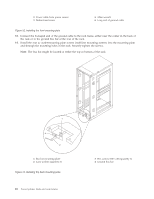
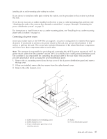
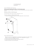
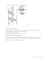
4 Power distribution panel top cover Figure 14. Removing the cable channel cover 4. Remove the -48 V dc bus bar shield from the power distribution panel. Attention: The bus bar shield must be correctly reinstalled over the -48 V dc return bus bars to protect against injury while servicing the power distribution panel. 5. Ensure that the following steps are performed when connecting the dc power source. a. At -48 V dc power source, turn off any -48 V dc power sources that will be connected to the power distribution panel. b. After the -48 V dc power sources are turned off, be sure there is a tag or label over the power source switches or fuses (lock-out/tag-out) to indicate that the power source is turned off intentionally. Note: Ensure that any oxidation on the copper bus bars is removed. c. If this is a raised-floor installation and you are working at the back of the rack, route the power cables up the rack's right side. d. Ensure that the external -48 V dc power cable is connected correctly to the -48 V dc bus bar. e. Ensure that the external -48 V dc return cable is routed correctly and installed on the return bus bar. 1 -48 V dc power cable and return power cable 2 Power distribution panel 3 Front of rack 4 -48 V dc power cable and return power cable Figure 15. Routing the power cables 18 Power Systems: Racks and rack features
-
 1
1 -
2
-
3
-
4
-
5
-
6
-
7
-
8
-
9
-
10
-
11
-
12
-
13
-
14
-
15
-
16
-
17
-
18
-
19
-
20
-
21
-
22
-
23
-
24
-
 25
25 -
 26
26 -
 27
27 -
 28
28 -
 29
29 -
 30
30 -
 31
31 -
 32
32 -
 33
33 -
 34
34 -
 35
35 -
36
-
37
-
38
-
39
-
40
-
41
-
42
-
43
-
44
-
45
-
46
-
47
-
48
-
49
-
50
-
51
-
52
-
53
-
54
-
55
-
56
-
57
-
58
-
59
-
60
-
61
-
62
-
63
-
64
-
65
-
66
-
67
-
68
-
69
-
70
-
71
-
72
-
73
-
74
 |
 |
