IBM 7014-T42 User Guide - Page 53
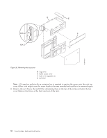
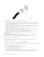
that was provided with the PDU model with the connector on the, front of the unit
 |
View all IBM 7014-T42 manuals
Add to My Manuals
Save this manual to your list of manuals |
Page 53 highlights
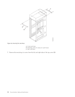
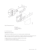
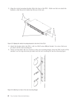
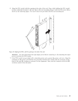
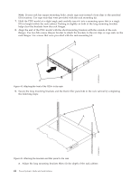
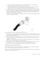
6. Align the PDU model with the opening in the side of the rack. Then, while holding the PDU model in place, attach the brackets to the nut clips in the rack mounting flanges with four M5 screws (A) as shown in the following figure. Use screws that were provided with the rack mounting kit. Figure 40. Aligning the PDU+ with the opening in the side of the rack Attention: You must disconnect the main input power before connecting or disconnecting the input power cord from the PDU model. 7. If the PDU model was provided with a detached power cord, connect the power cord now. Align the connector on the power cord (A) that was provided with the PDU model with the connector on the front of the unit (A), turning as necessary for key alignment. Then, turn the connector twist-lock (B) clockwise until it locks into place. Racks and rack features 41
-
 1
1 -
2
-
3
-
4
-
5
-
6
-
7
-
8
-
9
-
10
-
11
-
12
-
13
-
14
-
15
-
16
-
17
-
18
-
19
-
20
-
21
-
22
-
23
-
24
-
25
-
26
-
27
-
28
-
29
-
30
-
31
-
32
-
33
-
34
-
35
-
36
-
37
-
38
-
39
-
40
-
41
-
42
-
43
-
44
-
45
-
46
-
47
-
 48
48 -
 49
49 -
 50
50 -
 51
51 -
 52
52 -
 53
53 -
 54
54 -
 55
55 -
 56
56 -
 57
57 -
 58
58 -
59
-
60
-
61
-
62
-
63
-
64
-
65
-
66
-
67
-
68
-
69
-
70
-
71
-
72
-
73
-
74
 |
 |
