IBM 7014-T42 User Guide - Page 22
when reviewing the contents of the hardware mounting kit. The hardware mounting kit contains
 |
View all IBM 7014-T42 manuals
Add to My Manuals
Save this manual to your list of manuals |
Page 22 highlights
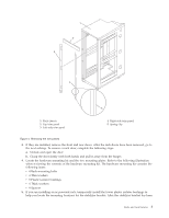
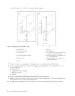
3 Left-side trim panel Figure 8. Removing the trim panels 3. If installed, remove the front and rear doors. For instructions, see "Attaching the rack doors" on page 24. After the rack doors have been removed, go to the next step. 4. Locate the hardware mounting kit and the two mounting plates. Refer to the following illustration when reviewing the contents of the hardware mounting kit. The hardware mounting kit contains the following items: v Four rack-mounting bolts v Four thin washers v Eight plastic isolator bushings v Four thick washers v Four spacers 5. If you are installing an ac-powered rack, temporarily install the lower plastic isolator bushings to help you locate the rack-mounting plate. After the mounting plate has been correctly located, remove the lower plastic isolator bushings. Figure 9. Installing the ac power-mounting plates 1 Rack chassis 2 Rack-mounting bolt 3 Thin washer 4 Top plastic isolator bushing 5 Thick washer 10 Power Systems: Racks and rack features 7 Jam nut 8 Leveling foot 9 Lower plastic isolator bushing (used only on dc powered systems) ac Typical leveling foot installation for an ac-powered rack dc Typical leveling foot installation for an dc-powered rack
-
 1
1 -
2
-
3
-
4
-
5
-
6
-
7
-
8
-
9
-
10
-
11
-
12
-
13
-
14
-
15
-
16
-
 17
17 -
 18
18 -
 19
19 -
 20
20 -
 21
21 -
 22
22 -
 23
23 -
 24
24 -
 25
25 -
 26
26 -
 27
27 -
28
-
29
-
30
-
31
-
32
-
33
-
34
-
35
-
36
-
37
-
38
-
39
-
40
-
41
-
42
-
43
-
44
-
45
-
46
-
47
-
48
-
49
-
50
-
51
-
52
-
53
-
54
-
55
-
56
-
57
-
58
-
59
-
60
-
61
-
62
-
63
-
64
-
65
-
66
-
67
-
68
-
69
-
70
-
71
-
72
-
73
-
74
 |
 |
