IBM 7014-T42 User Guide - Page 24
Insert each of the bolt assemblies through a leveling foot.
 |
View all IBM 7014-T42 manuals
Add to My Manuals
Save this manual to your list of manuals |
Page 24 highlights
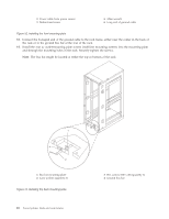
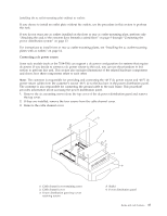
1 Rack-mounting bolt 2 Thin washer 3 Top plastic isolator bushing 4 Thick washer 5 Spacer 6 Jam nut 7 Leveling foot 8 Lower plastic isolator bushing (used only on dc-powered systems) 9 Stabilizer brackets 10 Threaded hole (used to secure the rack to mounting plate.) 11 Anchor bolt hole 12 Traced pattern (pattern to be traced onto the floor using the mounting plate as a template) Figure 10. Securing the rack to the floor 30. Using your anchor bolts, secure the back stabilizer bracket on top of the raised floor and through to the concrete floor. 31. Replace all raised-floor panels that may have been removed when aligning and securing the anchor bolts to the concrete floor. 32. Align the rack over the front and rear stabilizer brackets. 33. Insert each of the bolt assemblies through a leveling foot. 34. Align the rack-mounting bolts with the threaded holes in each stabilizer bracket. Turn each bolt three to four rotations. 35. Tighten the locking screw on each caster. 36. Adjust the leveling feet downward as needed until the rack is level. When the rack is level, tighten the jam nuts against the base of the rack. 37. If you have multiple racks that are connected as a suite (bolted to each other), go to "Connecting multiple racks with rack-to-rack attachment kit" on page 33. Otherwise, torque the four bolts to 54 67 newton-meters (40 - 50 foot-pounds). 38. If you are not installing doors on your rack, install the top, left, and right trim panel. 12 Power Systems: Racks and rack features
-
 1
1 -
2
-
3
-
4
-
5
-
6
-
7
-
8
-
9
-
10
-
11
-
12
-
13
-
14
-
15
-
16
-
17
-
18
-
 19
19 -
 20
20 -
 21
21 -
 22
22 -
 23
23 -
 24
24 -
 25
25 -
 26
26 -
 27
27 -
 28
28 -
 29
29 -
30
-
31
-
32
-
33
-
34
-
35
-
36
-
37
-
38
-
39
-
40
-
41
-
42
-
43
-
44
-
45
-
46
-
47
-
48
-
49
-
50
-
51
-
52
-
53
-
54
-
55
-
56
-
57
-
58
-
59
-
60
-
61
-
62
-
63
-
64
-
65
-
66
-
67
-
68
-
69
-
70
-
71
-
72
-
73
-
74
 |
 |
