IBM 7014-T42 User Guide - Page 57
Setting up power monitoring using the PDU+ - server rack
 |
View all IBM 7014-T42 manuals
Add to My Manuals
Save this manual to your list of manuals |
Page 57 highlights
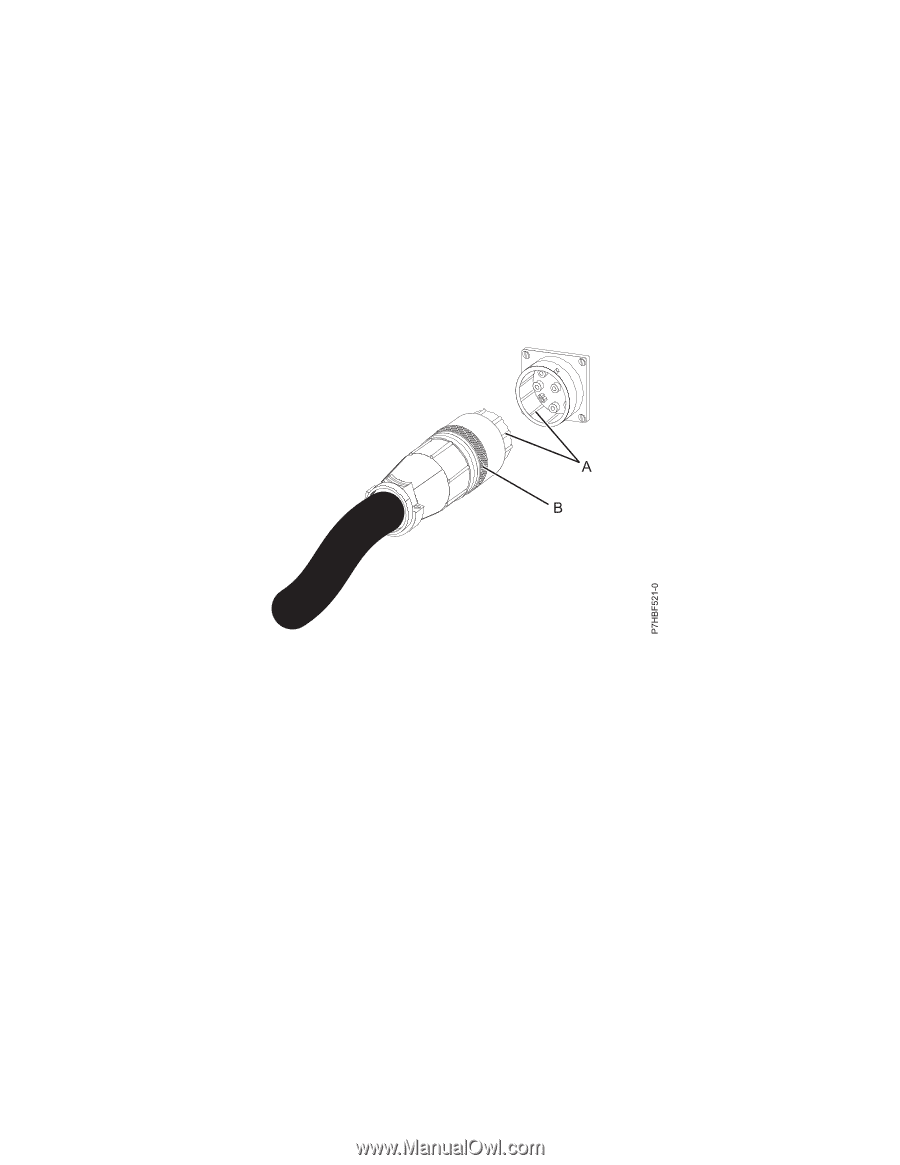
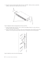
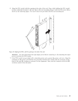
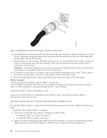
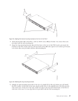
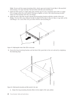
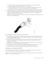
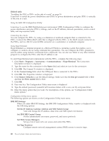
b. Make sure that the long mounting brackets are aligned with the inside of the rack flanges. c. Align the blank filler panel (B) on the outside of the rack flanges. d. Attach the filler panel to the rack flanges and then to the long mounting bracket with one M6 screw (C) per bracket. Use screws that were provided with the rack mounting kit. e. Tighten the M3 pan-head screws (D) that secure the long mounting brackets to the PDU model. 10. If the PDU model was provided with a detached power cord, connect the power cord now. Align the connector on the power cord (A) that was provided with the PDU model with the connector on the front of the unit (A), turning as necessary for key alignment. Then, turn the twist-lock (B) on the connector clockwise until it locks into place. Attention: You must disconnect the main input power before connecting or disconnecting the input power cord from the PDU model. Figure 46. Aligning the connector on the power cord with the PDU model 11. Route the power cord from the PDU model toward the rack side braces. Then, route the power cord along a side brace toward the back of the rack and secure the power cord with the cable straps that are provided with the PDU model. 12. Route the power cord toward a dedicated power source. Use the provided cable straps to secure the power cord along the way. Use the openings in the rack if the power cord must exit the rack to connect to a power source. Attention: To prevent damage to a power device and other connected devices, always connect the power device to an authorized power source for that device. 13. Connect the power cord to a properly wired and grounded dedicated power source. Then, you can connect the servers or rack PDUs in the rack to the power outlets on the PDU model. 14. Route all of the other power cables neatly, and secure the power cables with cable straps. Setting up power monitoring using the PDU+: You can monitor the power status for any device that is connected to the power distribution unit plus (PDU+), either manually or remotely, through the PDU+ web interface. Note: All of the Configuration Utility configuration options are available through the web interface after the PDU+ is set up on the local network. Racks and rack features 45
-
 1
1 -
2
-
3
-
4
-
5
-
6
-
7
-
8
-
9
-
10
-
11
-
12
-
13
-
14
-
15
-
16
-
17
-
18
-
19
-
20
-
21
-
22
-
23
-
24
-
25
-
26
-
27
-
28
-
29
-
30
-
31
-
32
-
33
-
34
-
35
-
36
-
37
-
38
-
39
-
40
-
41
-
42
-
43
-
44
-
45
-
46
-
47
-
48
-
49
-
50
-
51
-
 52
52 -
 53
53 -
 54
54 -
 55
55 -
 56
56 -
 57
57 -
 58
58 -
 59
59 -
 60
60 -
 61
61 -
 62
62 -
63
-
64
-
65
-
66
-
67
-
68
-
69
-
70
-
71
-
72
-
73
-
74
 |
 |