IBM x3500 User Guide - Page 28
System-board, internal, connectors, switches - internal usb
 |
UPC - 883436005760
View all IBM x3500 manuals
Add to My Manuals
Save this manual to your list of manuals |
Page 28 highlights
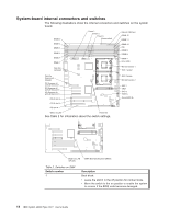
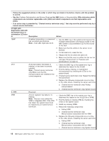
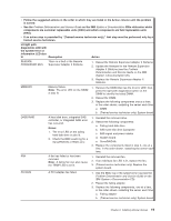
System-board internal connectors and switches The following illustrations show the internal connectors and switches on the system board. DIMM 6 DIMM 5 DIMM 4 DIMM 3 DIMM 2 DIMM 1 Rear fan (optional) Power 1 Power 2 Power 3 Power switch Internal USB tape DIMM 12 DIMM 11 DIMM 10 IDE DIMM 9 DIMM 8 DIMM 7 Front USB Microprocessor 1 SAS 1 power Remote Supervisor Adapter PCI Express x8 with x8 links slot 1 PCI Express x8 with x8 links slot 2 PCI Express x8 with x8 links slot 3 PCI-X slot 4 PCI-X slot 5 PCI slot 6 Wake on LAN Reserved See Table 2 for information about the switch settings. SAS 2 power Microprocessor 2 SAS 1 VRM SAS 2 Battery ServeRAID-8k Wake on LAN (CN 45) SW4 (Boot block/Clear CMOS) Table 2. Switches on SW4 Switch number 1 Description Boot block: v Leave the switch in the off position for normal mode. v Move the switch to the on position to enable the system to recover if the BIOS code becomes damaged. 14 IBM System x3500 Type 7977: User's Guide
-
 1
1 -
2
-
3
-
4
-
5
-
6
-
7
-
8
-
9
-
10
-
11
-
12
-
13
-
14
-
15
-
16
-
17
-
18
-
19
-
20
-
21
-
22
-
 23
23 -
 24
24 -
 25
25 -
 26
26 -
 27
27 -
 28
28 -
 29
29 -
 30
30 -
 31
31 -
 32
32 -
 33
33 -
34
-
35
-
36
-
37
-
38
-
39
-
40
-
41
-
42
-
43
-
44
-
45
-
46
-
47
-
48
-
49
-
50
-
51
-
52
-
53
-
54
-
55
-
56
-
57
-
58
-
59
-
60
-
61
-
62
-
63
-
64
-
65
-
66
-
67
-
68
-
69
-
70
-
71
-
72
-
73
-
74
-
75
-
76
-
77
-
78
-
79
-
80
-
81
-
82
-
83
-
84
-
85
-
86
-
87
-
88
-
89
-
90
-
91
-
92
-
93
-
94
-
95
-
96
-
97
-
98
-
99
-
100
-
101
-
102
-
103
-
104
 |
 |
