IBM x3500 User Guide - Page 48
Devices, Ports, Advanced, Chipset, Control, Memory, Branch, Mirror - memory configuration
 |
UPC - 883436005760
View all IBM x3500 manuals
Add to My Manuals
Save this manual to your list of manuals |
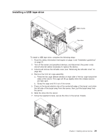
Page 48 highlights
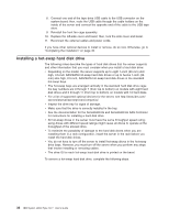
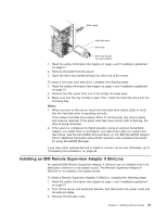
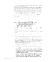
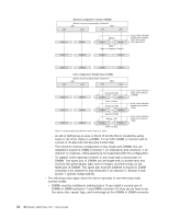
v When you install additional DIMMs, be sure to install them in pairs. All the DIMM pairs must be the same size and type. v The memory controller has four fully buffered DIMM channels that are organized into two branches. Each branch has two channels, and each channel controls two DIMMs. DIMMs that are next to each other (for example, in DIMM connector 1 and DIMM connector 4) within the channels of a branch must be identical in size, type, speed, and technology. However, the DIMMs in the connectors above or below each other within the channels of a branch do not have to be identical (for example, the DIMMs in DIMM connector 1 and DIMM connector 2 do not have to be identical). The following illustration shows how the memory controller is organized into branches and channels with two pairs of installed DIMMs. v You do not have to save new configuration information when you install or remove DIMMs. Branch 0 Branch 1 Channel 1 Channel 3 Channel 0 Channel 4 DIMM 6 DIMM 5 DIMM 4 DIMM 3 DIMM 2 DIMM 1 DIMM 12 DIMM 11 DIMM 10 DIMM 9 DIMM 8 DIMM 7 v The 12 DIMM connectors are divided between the two memory branches. DIMM connectors 1 through 6 are on branch 0, and DIMM connectors 7 through 12 are on branch 1. v The server can operate in two major modes: mirroring and non-mirroring (normal). The server can also operate in a single-channel mode when one DIMM is installed. v The server supports memory mirroring (mirroring mode) and online-spare memory. - Memory mirroring replicates and stores data on DIMMs within two branches simultaneously. You must enable memory mirroring through the Configuration/Setup Utility program (see "Using the Configuration/Setup Utility program" on page 50). To enable memory mirroring in the Configuration/Setup Utility program, select Devices and I/O Ports → Advanced Chipset Control → Memory Branch Mode. Use the arrow keys to change the Memory Branch Mode setting to Mirror; then, save your changes. When you use memory mirroring, consider the following information: - The maximum available memory is reduced to 16 GB, instead of the 32 GB available in non-mirroring mode. - The minimum memory configuration is four identical DIMMs. You must install identical pairs of fully buffered, dual-inline memory modules (DIMMs) in all four DIMM connectors (same size, type, speed, and technology). These DIMMs must span across both branches and all four channels. For example, when you install the first four DIMMs, you must install two DIMMs in branch 0 (one in channel 0 and one in channel 1) and two DIMMs in branch 1 (one in channel 2 and one in channel 3). See Table 3 on page 35 for the DIMM installation sequence. - When you upgrade the server to eight DIMMs, the DIMMs that are next to each other (for example, DIMM connector 1 and DIMM connector 4) within the channels of a branch must be identical in size, type, speed, and technology. However, the DIMMs in the connectors above or below each 34 IBM System x3500 Type 7977: User's Guide
-
 1
1 -
2
-
3
-
4
-
5
-
6
-
7
-
8
-
9
-
10
-
11
-
12
-
13
-
14
-
15
-
16
-
17
-
18
-
19
-
20
-
21
-
22
-
23
-
24
-
25
-
26
-
27
-
28
-
29
-
30
-
31
-
32
-
33
-
34
-
35
-
36
-
37
-
38
-
39
-
40
-
41
-
42
-
 43
43 -
 44
44 -
 45
45 -
 46
46 -
 47
47 -
 48
48 -
 49
49 -
 50
50 -
 51
51 -
 52
52 -
 53
53 -
54
-
55
-
56
-
57
-
58
-
59
-
60
-
61
-
62
-
63
-
64
-
65
-
66
-
67
-
68
-
69
-
70
-
71
-
72
-
73
-
74
-
75
-
76
-
77
-
78
-
79
-
80
-
81
-
82
-
83
-
84
-
85
-
86
-
87
-
88
-
89
-
90
-
91
-
92
-
93
-
94
-
95
-
96
-
97
-
98
-
99
-
100
-
101
-
102
-
103
-
104
 |
 |
