IBM x3500 User Guide - Page 51
System, Summary
 |
UPC - 883436005760
View all IBM x3500 manuals
Add to My Manuals
Save this manual to your list of manuals |
Page 51 highlights
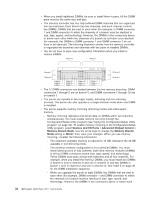
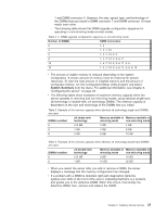
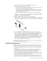
1 and DIMM connector 4. However, the size, speed, type, and technology of the DIMMs that you install in DIMM connector 7 and DIMM connector 10 must match each other. - The following table shows the DIMM upgrade configuration sequence for operating in non-mirroring mode (normal mode). Table 4. 5. DIMM upgrade configuration sequence in non-mirroring mode Number of DIMMs DIMM connectors 2 1, 4 4 1, 4, 7, 10 6 1, 4, 7, 10, 2, 5 8 1, 4, 7, 10, 2, 5, 8, 11 10 1, 4, 7, 10, 2, 5, 8, 11, 3, 6 12 1, 4, 7, 10, 2, 5, 8, 11, 3, 6, 9, 12 v The amount of usable memory is reduced depending on the system configuration. A certain amount of memory must be reserved for system resources. To view the total amount of installed memory and the amount of configured memory, run the Configuration/Setup Utility program and select System Summary from the menu. For additional information, see Chapter 3, "Configuring the server," on page 49. v The following tables show examples of maximum memory capacity when the server operates in mirroring and non-mirroring modes, using identical single-rank, x8 technology or double-rank, x4 technology DIMMs. The memory capacity is dependent on the size and technology of the DIMMs that you install. Table 5. Example of the memory capacity when identical x8 technology single-rank DIMMs are used DIMMs installed x8 single-rank technology Memory available in Memory available in mirroring mode non-mirroring mode 8 512 MB 2 GB 4 GB 8 1 GB 4 GB 8 GB 8 2 GB 8 GB 16 GB Table 6. Example of the memory capacity when identical x4 technology double-rank DIMMs are used DIMMs installed x4 double-rank technology Memory available in Memory available in mirroring mode non-mirroring mode 8 512 MB 8 GB 16 GB 8 1 GB 16 GB 32 GB v When you restart the server after you add or remove a DIMM, the server displays a message that the memory configuration has changed. v If a problem with a DIMM is detected, light path diagnostics lights the system-error LED on the front of the server, indicating that there is a problem, and guides you to the defective DIMM. When this occurs, first identify the defective DIMM; then, remove and replace the DIMM. Chapter 2. Installing optional devices 37
-
 1
1 -
2
-
3
-
4
-
5
-
6
-
7
-
8
-
9
-
10
-
11
-
12
-
13
-
14
-
15
-
16
-
17
-
18
-
19
-
20
-
21
-
22
-
23
-
24
-
25
-
26
-
27
-
28
-
29
-
30
-
31
-
32
-
33
-
34
-
35
-
36
-
37
-
38
-
39
-
40
-
41
-
42
-
43
-
44
-
45
-
 46
46 -
 47
47 -
 48
48 -
 49
49 -
 50
50 -
 51
51 -
 52
52 -
 53
53 -
 54
54 -
 55
55 -
 56
56 -
57
-
58
-
59
-
60
-
61
-
62
-
63
-
64
-
65
-
66
-
67
-
68
-
69
-
70
-
71
-
72
-
73
-
74
-
75
-
76
-
77
-
78
-
79
-
80
-
81
-
82
-
83
-
84
-
85
-
86
-
87
-
88
-
89
-
90
-
91
-
92
-
93
-
94
-
95
-
96
-
97
-
98
-
99
-
100
-
101
-
102
-
103
-
104
 |
 |
