Intel S1200RP Service Guide - Page 69
Map of Screens and Functionality
 |
View all Intel S1200RP manuals
Add to My Manuals
Save this manual to your list of manuals |
Page 69 highlights
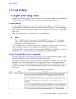
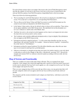
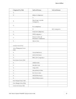
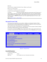
Server Utilities For each of these screens, there is an image of the screen with a list of Field Descriptions which describe the contents of each item on the screen. Each item on the screen is hyperlinked to the relevant Field Description. Each Field Description is hyperlinked back to the screen image. These lists follow the following guidelines: The text heading for each Field Description is the actual text as displayed on the BIOS Setup screen. This screen text is a hyperlink to its corresponding Field Description. The text shown in the Option Values and Help Text entries in each Field Description are the actual text and values are displayed on the BIOS Setup screens. In the Option Values entries, the text for default values is shown with an underline. These values do not appear underline on the BIOS Setup screen. The underlined text in this document is to serve as a reference to which value is the default value. The Help Text entry is the actual text which appears on the screen to accompany the item when the item is the one in focus (active on the screen). The Comments entry provides additional information where it may be helpful. This information does not appear on the BIOS Setup screens. Information enclosed in angular brackets (< >) in the screen shots identifies text that can vary, depending on the option(s) installed. For example, is replaced by the actual value for "Total Memory". Information enclosed in square brackets ([ ]) in the tables identifies areas where the user must type in text instead of selecting from a provided option. Whenever information is changed (except Date and Time), the systems requires a save and reboot to take place in order for the changes to take effect. Alternatively, pressing discards the changes and resumes POST to continue to boot the system according to the boot order set from the last boot. Map of Screens and Functionality There are a number of screens in the entire Setup collection. They are organized into major categories. Each category has a hierarchy beginning with a top-level screen from which lower-level screens may be selected. Each top-level screen appears as a tab, arranged across the top of the Setup screen image of all top-level screens. There are more categories than will fit across the top of the screen, so at any given time there will be some categories which will not appear until the user has scrolled across the tabs which are present. The categories and the screens included in each category are listed below, with links to each of the screens named. Table 6. Screen Map Categories (Top Tabs) Main Screen (Tab) Advanced Screen (Tab) 2nd Level Screens Processor Configuration 3rd Level Screens 56 Intel® Server System P4000RP Family Service Guide
-
 1
1 -
2
-
3
-
4
-
5
-
6
-
7
-
8
-
9
-
10
-
11
-
12
-
13
-
14
-
15
-
16
-
17
-
18
-
19
-
20
-
21
-
22
-
23
-
24
-
25
-
26
-
27
-
28
-
29
-
30
-
31
-
32
-
33
-
34
-
35
-
36
-
37
-
38
-
39
-
40
-
41
-
42
-
43
-
44
-
45
-
46
-
47
-
48
-
49
-
50
-
51
-
52
-
53
-
54
-
55
-
56
-
57
-
58
-
59
-
60
-
61
-
62
-
63
-
 64
64 -
 65
65 -
 66
66 -
 67
67 -
 68
68 -
 69
69 -
 70
70 -
 71
71 -
 72
72 -
 73
73 -
 74
74 -
75
-
76
-
77
-
78
-
79
-
80
-
81
-
82
-
83
-
84
-
85
-
86
-
87
-
88
-
89
-
90
-
91
-
92
-
93
-
94
-
95
-
96
-
97
-
98
-
99
-
100
-
101
-
102
-
103
-
104
-
105
-
106
-
107
-
108
-
109
-
110
-
111
-
112
-
113
-
114
-
115
-
116
-
117
-
118
-
119
-
120
-
121
-
122
-
123
-
124
-
125
-
126
-
127
-
128
-
129
-
130
-
131
-
132
-
133
-
134
-
135
-
136
-
137
-
138
-
139
-
140
-
141
-
142
-
143
-
144
-
145
-
146
-
147
-
148
-
149
-
150
-
151
-
152
-
153
-
154
-
155
-
156
-
157
-
158
-
159
-
160
-
161
-
162
-
163
 |
 |
