JVC HM-DH30000UP 84 pg. instruction manual on the HM-DH30000U D-VHS recorder/p - Page 7
Connections
 |
View all JVC HM-DH30000UP manuals
Add to My Manuals
Save this manual to your list of manuals |
Page 7 highlights
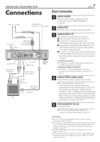
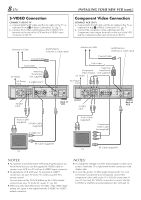
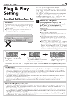
INSTALLING YOUR NEW VCR Connections Antenna or Cable ANTENNA IN (Antenna or cable input) Coaxial Cable Flat Feeder AC Outlet AC Power Cord Matching Transformer (not supplied) Y PB/CB PR/CR R AUDIO L VIDEO OUT IN(L-1) R AUDIO L(MONO) VIDEO S VIDEO OUT IN(L-2) IN S VIDEO CABLE BOX VHF/UHF ANTENNA IN REMOTE PAUSE/ AV COMPU LINK TV OUT i.LINK IN/OUT DV IN S200 DIGITAL OUT OPTICAL PCM/DOLBY DIGITAL AUDIO OUT TV OUT VIDEO OUT Audio Cable (supplied) To Audio Input Connectors Video Cable (not supplied) To Video Input Connectors RF Cable (supplied) To 75 Ω termninal Back of VCR TV Basic Connection EN 7 1 Check contents Make sure the package contains all of the accessories listed in "SPECIFICATIONS" (੬ pg. 81). 2 Situate VCR Place the VCR on a stable, horizontal surface. 3 Connect VCR to TV The following connections are required. 1 Disconnect the TV antenna from the TV. 2 Connect the TV antenna cable to the ANTENNA IN terminal on the rear of the VCR. 3 Connect the supplied RF cable between the TV OUT terminal on the rear of the VCR and the TV's antenna input terminal. 4 Connect an audio/video cable between the AUDIO/VIDEO OUT connectors on the rear of the VCR and the audio/video input connectors on the TV. S-VIDEO Connection ● If you have a TV with S-VIDEO input terminals, see "S-VIDEO Connection" on page 8. Component Video Connection ● If you have a TV with component video input terminals, see "Component Video Connection" on page 8. 4 Connect VCR to power source Connect the AC power plug to the AC outlet. ● The clock and tuner channels will automatically be set when the antenna is connected and when the AC power cord is first connected to an AC power outlet (੬ pg. 9). (If "Auto" or "CH" is displayed on the front display panel before the VCR is turned on, the clock and tuner channels are being set automatically. Wait until the clock time is displayed on the front display panel before turning on the VCR.) 5 Final preparation for use Turn on the VCR. ● You can now perform basic playback (੬ pg. 21) or basic recording (੬ pg. 26). NOTES: ● Your TV must have audio/video input connector for the connection to the recorder. ● Even if you are using audio/video cables to connect your VCR to your TV, you must also connect it using the RF cable. This will ensure that you can record one show while watching another (੬ pg. 29). ● For full identification of the VCR's rear panel, refer to the Index ( ੬ pg. 77). ● When you play back the picture of 1080i, 720p, 480p image format, the signal is not output from the S-VIDEO or VIDEO output connector.
-
 1
1 -
 2
2 -
 3
3 -
 4
4 -
 5
5 -
 6
6 -
 7
7 -
 8
8 -
 9
9 -
 10
10 -
 11
11 -
 12
12 -
13
-
14
-
15
-
16
-
17
-
18
-
19
-
20
-
21
-
22
-
23
-
24
-
25
-
26
-
27
-
28
-
29
-
30
-
31
-
32
-
33
-
34
-
35
-
36
-
37
-
38
-
39
-
40
-
41
-
42
-
43
-
44
-
45
-
46
-
47
-
48
-
49
-
50
-
51
-
52
-
53
-
54
-
55
-
56
-
57
-
58
-
59
-
60
-
61
-
62
-
63
-
64
-
65
-
66
-
67
-
68
-
69
-
70
-
71
-
72
-
73
-
74
-
75
-
76
-
77
-
78
-
79
-
80
-
81
-
82
-
83
-
84
 |
 |
