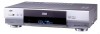
JVC HM-DH30000UP 84 pg. instruction manual on the HM-DH30000U D-VHS recorder/p - Page 77
Rear panel
 |
View all JVC HM-DH30000UP manuals
Add to My Manuals
Save this manual to your list of manuals |
Page 77 highlights
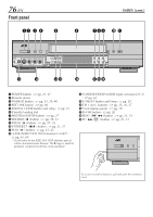
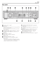
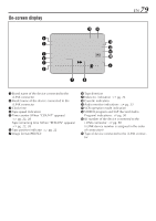
Rear panel 12 3 EN 77 4 5 67 8 Y PB/CB PR/CR R AUDIO L VIDEO OUT IN(L-1) R AUDIO L(MONO) VIDEO S VIDEO OUT IN(L-2) IN S VIDEO CABLE BOX VHF/UHF ANTENNA IN REMOTE PAUSE/ AV COMPULINK TV OUT i.LINK IN/OUT DV IN S200 DIGITAL OUT OPTICAL PCM/DOLBY DIGITAL 9 0 !@ # 1 AC power cord : ੬ pg. 7 2 Cooling fan ● This prevents the temperature from rising inside the VCR. Do not remove it. ● Install the VCR so as not to block the area around the cooling fan. 3 Component video output connectors : ੬ pg. 8 4 S VIDEO/AUDIO/VIDEO IN connectors (L-1): ੬ pg. 64 5 JLIP terminal : ੬ pg. 61 6 CABLE BOX Controller connector : ੬ pg. 15, 18 7 ANTENNA IN terminal : ੬ pg. 7 8 i.LINK IN/OUT, DV IN Connector (i.Link*) : ੬ pg. 62, 64 * i.Link refers to the IEEE1394-1995 industry specifi- cation and extensions thereof. The logo is used for products compliant with the i.Link standard. 9 S VIDEO/AUDIO/VIDEO OUT connectors : ੬␣ pg. 8, 64 0 S VIDEO/AUDIO/VIDEO IN connectors (L-2): ੬ pg. 64 ! REMOTE PAUSE/AV COMPULINK terminal ● REMOTE PAUSE terminal : ੬ pg. 62 ● AV COMPULINK terminal : ੬ pg. 57 @ TV OUT terminal : ੬ pg. 7 # DIGITAL OUT OPTICAL terminal : ੬ pg. 54
-
 1
1 -
2
-
3
-
4
-
5
-
6
-
7
-
8
-
9
-
10
-
11
-
12
-
13
-
14
-
15
-
16
-
17
-
18
-
19
-
20
-
21
-
22
-
23
-
24
-
25
-
26
-
27
-
28
-
29
-
30
-
31
-
32
-
33
-
34
-
35
-
36
-
37
-
38
-
39
-
40
-
41
-
42
-
43
-
44
-
45
-
46
-
47
-
48
-
49
-
50
-
51
-
52
-
53
-
54
-
55
-
56
-
57
-
58
-
59
-
60
-
61
-
62
-
63
-
64
-
65
-
66
-
67
-
68
-
69
-
70
-
71
-
 72
72 -
 73
73 -
 74
74 -
 75
75 -
 76
76 -
 77
77 -
 78
78 -
 79
79 -
 80
80 -
 81
81 -
 82
82 -
83
-
84
 |
 |
