JVC HM-DH30000UP 84 pg. instruction manual on the HM-DH30000U D-VHS recorder/p - Page 76
Front panel
 |
View all JVC HM-DH30000UP manuals
Add to My Manuals
Save this manual to your list of manuals |
Page 76 highlights
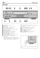
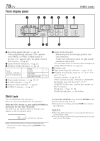
76 EN Front panel 12 3 4 5 INDEX (cont.) 6 789 0 ! POWER TIMER REC LINC i.LINK IN/OUT S-VIDEO DV IN VIDEO (MONO) L AUDIO R S200 IN I - MENU IN F-1 DIGITAL 3-D NR 3DNR S-VHS ET CH S-ET @ # $% ^ STOP/EJECT PLAY HS/STD/LS3 REC PAUSE SP/EP D-VHS REW FF &*( 1 POWER button : ੬ pg. 21, 27 2 Remote sensor 3 TIMER ‰ button : ੬ pg. 35, 39, 40 4 REC LINK button : ੬ pg. 60 5 DIGITAL 3-DNR button and lamp : ੬ pg. 25 6 Cassette loading slot 7 HS/STD/LS3/SP/EP button : ੬ pg. 27 8 RECORD ( ¶ ) button : ੬ pg. 26, 27 9 PAUSE ( 8 ) button : ੬ pg. 27, 32 0 STOP/EJECT ( 7/0 ) button : ੬ pg. 21, 27 ! PLAY ( 3 ) button : ੬ pg. 21, 23 @ i.LINK IN/OUT (DV IN) Connector (i.Link*) : ੬ pg. 62, 64 * i.Link refers to the IEEE1394-1995 industry specifi- cation and extensions thereof. The logo is used for products compliant with the i.Link standard. # S-VIDEO/VIDEO/AUDIO input connectors (F-1) : ੬ pg. 62 $ S-VHS ET button and lamp : ੬ pg. 29 % CH + and - buttons : ੬ pg. 23, 26, 27 ^ Front display panel : ੬ pg. 78 & D-VHS button : ੬ pg. 26 * REW ( 1 ) button : ੬ pg. 21, 31 ( FF ( ¡ ) button : ੬ pg. 21, 31 POWER TIMER REC LINK PULL-OPEN To access covered connectors, pull and open the connector cover.
-
 1
1 -
2
-
3
-
4
-
5
-
6
-
7
-
8
-
9
-
10
-
11
-
12
-
13
-
14
-
15
-
16
-
17
-
18
-
19
-
20
-
21
-
22
-
23
-
24
-
25
-
26
-
27
-
28
-
29
-
30
-
31
-
32
-
33
-
34
-
35
-
36
-
37
-
38
-
39
-
40
-
41
-
42
-
43
-
44
-
45
-
46
-
47
-
48
-
49
-
50
-
51
-
52
-
53
-
54
-
55
-
56
-
57
-
58
-
59
-
60
-
61
-
62
-
63
-
64
-
65
-
66
-
67
-
68
-
69
-
70
-
 71
71 -
 72
72 -
 73
73 -
 74
74 -
 75
75 -
 76
76 -
 77
77 -
 78
78 -
 79
79 -
 80
80 -
 81
81 -
82
-
83
-
84
 |
 |
