Lenovo Storage N3310 (English) User Guide and Hardware Maintenance Manual - Le - Page 62
Installing or removing a memory module, Memory module installation rules
 |
View all Lenovo Storage N3310 manuals
Add to My Manuals
Save this manual to your list of manuals |
Page 62 highlights
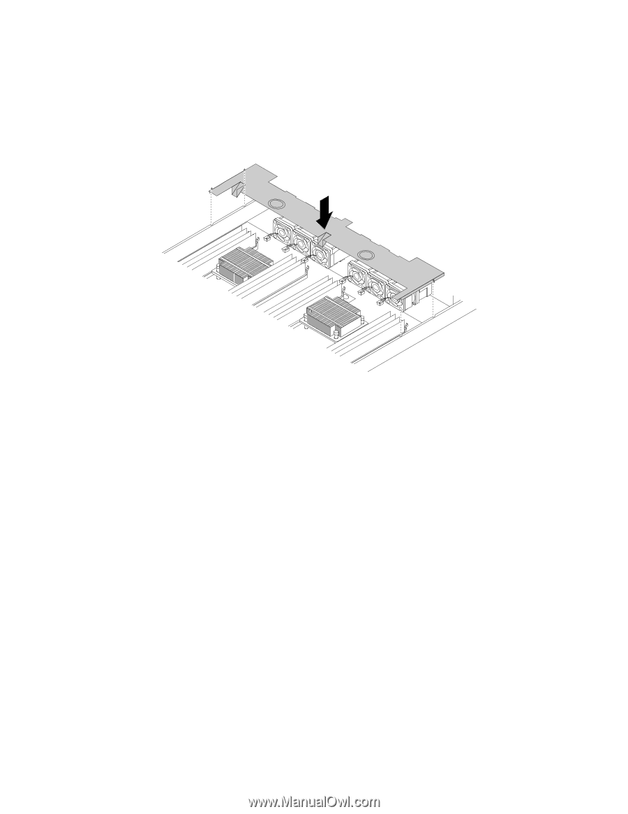
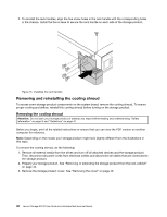
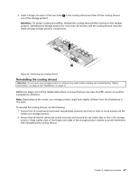
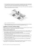
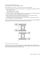
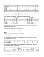
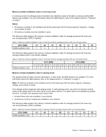
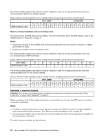
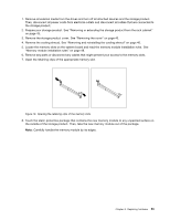
3. Note the orientation of the cooling shroud and then place it above the storage product so that the tabs on both sides of the cooling shroud are aligned with the corresponding holes or gaps in both sides of the chassis. Then, lower the cooling shroud into the chassis until it snaps into position. Note: If necessary, gently press the cooling shroud on both sides so that the tabs on the cooling shroud completely engage with both sides of the chassis. Figure 17. Reinstalling the cooling shroud 4. Reinstall the storage product cover and reconnect cables to the storage product. For more information, refer to "Reinstalling the storage product cover and reconnecting cables" on page 112. Installing or removing a memory module Note: The memory modules are extremely sensitive to ESD. Ensure that you read and understand "Handling static-sensitive devices" on page 42 first and carefully perform the operation. Memory module installation rules Your storage product has 16 memory slots. The following list describes the memory module installation rules. • Each slot supports 4 GB, 8 GB, and 16 GB double data rate 4 registered dual inline memory modules (DDR4 RDIMMs) with Error Checking and Correcting (ECC) technology. • Each slot supports 32 GB double data rate 4 load reduction dual inline memory modules (DDR4 LRDIMMs) with ECC technology. • Your storage product supports up to eight memory modules when one microprocessor is installed. Your storage product supports up to 16 memory modules when two microprocessors are installed. • The minimum system memory is 4 GB (only one microprocessor installed and only one 4 GB RDIMM installed in the CPU1 DIMMA1 slot). • The maximum system memory is 512 GB (two microprocessors installed and one 32 GB LRDIMM installed in each of the 16 memory slots). For more information about the memory modules in your specific storage product model, use the Setup Utility program. See "Viewing information in the Setup Utility program" on page 31. 48 Lenovo Storage N3310 User Guide and Hardware Maintenance Manual
-
 1
1 -
2
-
3
-
4
-
5
-
6
-
7
-
8
-
9
-
10
-
11
-
12
-
13
-
14
-
15
-
16
-
17
-
18
-
19
-
20
-
21
-
22
-
23
-
24
-
25
-
26
-
27
-
28
-
29
-
30
-
31
-
32
-
33
-
34
-
35
-
36
-
37
-
38
-
39
-
40
-
41
-
42
-
43
-
44
-
45
-
46
-
47
-
48
-
49
-
50
-
51
-
52
-
53
-
54
-
55
-
56
-
 57
57 -
 58
58 -
 59
59 -
 60
60 -
 61
61 -
 62
62 -
 63
63 -
 64
64 -
 65
65 -
 66
66 -
 67
67 -
68
-
69
-
70
-
71
-
72
-
73
-
74
-
75
-
76
-
77
-
78
-
79
-
80
-
81
-
82
-
83
-
84
-
85
-
86
-
87
-
88
-
89
-
90
-
91
-
92
-
93
-
94
-
95
-
96
-
97
-
98
-
99
-
100
-
101
-
102
-
103
-
104
-
105
-
106
-
107
-
108
-
109
-
110
-
111
-
112
-
113
-
114
-
115
-
116
-
117
-
118
-
119
-
120
-
121
-
122
-
123
-
124
-
125
-
126
-
127
-
128
-
129
-
130
-
131
-
132
-
133
-
134
-
135
-
136
-
137
-
138
-
139
-
140
-
141
-
142
-
143
-
144
-
145
-
146
-
147
-
148
-
149
-
150
-
151
-
152
 |
 |