Lenovo Storage N3310 (English) User Guide and Hardware Maintenance Manual - Le - Page 65
Memory module installation order in mirroring mode, Notes
 |
View all Lenovo Storage N3310 manuals
Add to My Manuals
Save this manual to your list of manuals |
Page 65 highlights
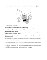
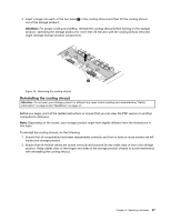
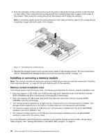
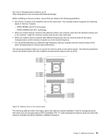
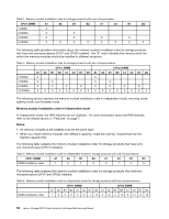
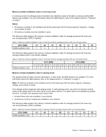
Memory module installation order in mirroring mode In mirroring mode, the storage product maintains two identical copies of all data in memory and the RAS features are available. For more information about the RAS features, refer to the related section in "Features" on page 7. Notes: • All memory modules to be installed must be the same type with the same capacity, frequency, voltage, and number of ranks. • All memory modules must be installed in pairs. The following table explains the memory module installation order for storage products that have only one microprocessor (CPU1) installed. Table 5. Memory module installation order in mirroring mode for storage products with one microprocessor CPU1 DIMM A1 A2 B1 B2 C1 C2 D1 D2 DIMM installation order 1 3 1 3 2 4 2 4 The following table explains the memory module installation order for storage products that have two microprocessors (CPU1 and CPU2) installed. Table 6. Memory module installation order in mirroring mode for storage products with two microprocessors CPU1 DIMM CPU2 DIMM A1 A2 B1 B2 C1 C2 D1 D2 A1 A2 B1 B2 C1 C2 D1 D2 DIMM installation order 15 15373726264848 Memory module installation order in sparing mode The sparing mode provides memory redundancy. In this mode, the RAS features are available. For more information about the RAS features, refer to the related section in "Features" on page 7. Note: All memory modules to be installed must be the same type with the same capacity, frequency, voltage, and number of ranks. Your storage product supports rank sparing mode. In rank sparing mode, one rank of a memory module works as the spare rank for the other ranks on the same channel. The spare rank is not available as system memory. To enable rank sparing mode, ensure that: • At least three ranks are available in one channel. • At least two memory modules are installed in one channel. The following table explains the memory module installation order for storage products that have only one microprocessor (CPU1) installed. Table 7. Memory module installation order in sparing mode for storage products with one microprocessor CPU1 DIMM A1 A2 B1 B2 C1 C2 D1 D2 DIMM installation order 1 1 2 2 3 3 4 4 Chapter 6. Replacing hardware 51
-
 1
1 -
2
-
3
-
4
-
5
-
6
-
7
-
8
-
9
-
10
-
11
-
12
-
13
-
14
-
15
-
16
-
17
-
18
-
19
-
20
-
21
-
22
-
23
-
24
-
25
-
26
-
27
-
28
-
29
-
30
-
31
-
32
-
33
-
34
-
35
-
36
-
37
-
38
-
39
-
40
-
41
-
42
-
43
-
44
-
45
-
46
-
47
-
48
-
49
-
50
-
51
-
52
-
53
-
54
-
55
-
56
-
57
-
58
-
59
-
 60
60 -
 61
61 -
 62
62 -
 63
63 -
 64
64 -
 65
65 -
 66
66 -
 67
67 -
 68
68 -
 69
69 -
 70
70 -
71
-
72
-
73
-
74
-
75
-
76
-
77
-
78
-
79
-
80
-
81
-
82
-
83
-
84
-
85
-
86
-
87
-
88
-
89
-
90
-
91
-
92
-
93
-
94
-
95
-
96
-
97
-
98
-
99
-
100
-
101
-
102
-
103
-
104
-
105
-
106
-
107
-
108
-
109
-
110
-
111
-
112
-
113
-
114
-
115
-
116
-
117
-
118
-
119
-
120
-
121
-
122
-
123
-
124
-
125
-
126
-
127
-
128
-
129
-
130
-
131
-
132
-
133
-
134
-
135
-
136
-
137
-
138
-
139
-
140
-
141
-
142
-
143
-
144
-
145
-
146
-
147
-
148
-
149
-
150
-
151
-
152
 |
 |
