Lexmark Forms Printer 2400 Service Manual - Page 52
Board /Cable Asm, Tractor 2 Motor
 |
View all Lexmark Forms Printer 2400 manuals
Add to My Manuals
Save this manual to your list of manuals |
Page 52 highlights
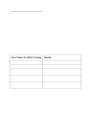
24xx FRU 2 Logic Board Action Remove Tractor 2 from the printer but leave the cable connected. Be sure the slider (the black plastic piece just above the right cover) moves after turning the printer off and then on. If the slider does not move after turning the printer off and then on: • Be sure the slider and gear train are properly connected and move freely with the power off. • Be sure the Tractor 2 board is receiving: +40 V dc on CN1-1 and +5 V dc on CN1-5. If not, check the cable connection and the voltages at logic board CN10-1. The upper right pin at CN10 is pin 1 (+40 V dc) and the pin just beneath it is pin 5 (+5 V dc). If these voltages are not present replace the logic board. 3 Tractor 2 Motor Check the resistances of the Tractor 2 motor Board /Cable Asm windings at CN5 on the Tractor 2 board. There should be 101 ± 5 ohms between pins: CN5 -1 and CN5 - 4 CN5 -1 and CN5 - 6 CN5 -2 and CN5 - 3 CN5 -2 and CN5 - 5 If the motor is good, replace the board / cable assembly. For information on the Tractor 2 cable connectors, see "Tractor 2 Cable Connectors" on page 5-26. 2-34 Service Manual
-
 1
1 -
2
-
3
-
4
-
5
-
6
-
7
-
8
-
9
-
10
-
11
-
12
-
13
-
14
-
15
-
16
-
17
-
18
-
19
-
20
-
21
-
22
-
23
-
24
-
25
-
26
-
27
-
28
-
29
-
30
-
31
-
32
-
33
-
34
-
35
-
36
-
37
-
38
-
39
-
40
-
41
-
42
-
43
-
44
-
45
-
46
-
 47
47 -
 48
48 -
 49
49 -
 50
50 -
 51
51 -
 52
52 -
 53
53 -
 54
54 -
 55
55 -
 56
56 -
 57
57 -
58
-
59
-
60
-
61
-
62
-
63
-
64
-
65
-
66
-
67
-
68
-
69
-
70
-
71
-
72
-
73
-
74
-
75
-
76
-
77
-
78
-
79
-
80
-
81
-
82
-
83
-
84
-
85
-
86
-
87
-
88
-
89
-
90
-
91
-
92
-
93
-
94
-
95
-
96
-
97
-
98
-
99
-
100
-
101
-
102
-
103
-
104
-
105
-
106
-
107
-
108
-
109
-
110
-
111
-
112
-
113
-
114
-
115
-
116
-
117
-
118
-
119
-
120
-
121
-
122
-
123
-
124
-
125
-
126
-
127
-
128
-
129
-
130
-
131
-
132
-
133
-
134
-
135
-
136
-
137
-
138
-
139
-
140
-
141
-
142
-
143
-
144
-
145
-
146
-
147
-
148
-
149
-
150
-
151
-
152
-
153
-
154
-
155
-
156
-
157
-
158
-
159
-
160
-
161
-
162
-
163
-
164
-
165
-
166
-
167
-
168
-
169
-
170
 |
 |
