Lexmark Forms Printer 2400 Service Manual - Page 71
Covers, Operator Panel Assembly Removal, While holding the latches down
 |
View all Lexmark Forms Printer 2400 manuals
Add to My Manuals
Save this manual to your list of manuals |
Page 71 highlights
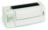
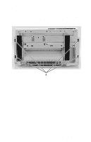
24xx Covers, Operator Panel Assembly Removal 1. Remove the top cover. Go to "Covers, Top Removal" on page 4-8. 2. Disconnect the operator panel cable from the operator panel card, on the inside of the top cover. 3. Push down on the two latches [A] at the top of the operator panel on the inside of the top cover, as shown. 4. While holding the latches down, push the operator panel out of the top cover, toward the bottom of the cover. Note: Be sure the operator panel cable is correctly inserted during replacement, into both the operator panel card and the logic board. Repair Information 4-11
-
 1
1 -
2
-
3
-
4
-
5
-
6
-
7
-
8
-
9
-
10
-
11
-
12
-
13
-
14
-
15
-
16
-
17
-
18
-
19
-
20
-
21
-
22
-
23
-
24
-
25
-
26
-
27
-
28
-
29
-
30
-
31
-
32
-
33
-
34
-
35
-
36
-
37
-
38
-
39
-
40
-
41
-
42
-
43
-
44
-
45
-
46
-
47
-
48
-
49
-
50
-
51
-
52
-
53
-
54
-
55
-
56
-
57
-
58
-
59
-
60
-
61
-
62
-
63
-
64
-
65
-
 66
66 -
 67
67 -
 68
68 -
 69
69 -
 70
70 -
 71
71 -
 72
72 -
 73
73 -
 74
74 -
 75
75 -
 76
76 -
77
-
78
-
79
-
80
-
81
-
82
-
83
-
84
-
85
-
86
-
87
-
88
-
89
-
90
-
91
-
92
-
93
-
94
-
95
-
96
-
97
-
98
-
99
-
100
-
101
-
102
-
103
-
104
-
105
-
106
-
107
-
108
-
109
-
110
-
111
-
112
-
113
-
114
-
115
-
116
-
117
-
118
-
119
-
120
-
121
-
122
-
123
-
124
-
125
-
126
-
127
-
128
-
129
-
130
-
131
-
132
-
133
-
134
-
135
-
136
-
137
-
138
-
139
-
140
-
141
-
142
-
143
-
144
-
145
-
146
-
147
-
148
-
149
-
150
-
151
-
152
-
153
-
154
-
155
-
156
-
157
-
158
-
159
-
160
-
161
-
162
-
163
-
164
-
165
-
166
-
167
-
168
-
169
-
170
 |
 |

Repair Information
4-11
24xx
Covers, Operator Panel Assembly Removal
1.
Remove the top cover. Go to
“Covers, Top Removal” on
page 4-8
.
2.
Disconnect the operator panel cable from the operator panel
card, on the inside of the top cover.
3.
Push down on the two latches [
A
] at the top of the operator
panel on the inside of the top cover, as shown.
4.
While holding the latches down, push the operator panel out of
the top cover, toward the bottom of the cover.
Note:
Be sure the operator panel cable is correctly inserted during
replacement, into both the operator panel card and the logic board.