Lexmark Forms Printer 2400 Service Manual - Page 87
Printhead Removal, Gap Adjustment procedure. Go
 |
View all Lexmark Forms Printer 2400 manuals
Add to My Manuals
Save this manual to your list of manuals |
Page 87 highlights
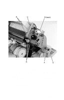
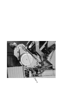
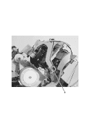
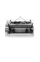
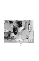
24xx Printhead Removal 1. Turn the printer off. 2. Disconnect the power cord at the printer and allow the printhead to cool for 15 minutes, prior to handling. 3. Set the form thickness lever to position 7. 4. Remove the ribbon access cover. Go to "Covers, Ribbon Access Removal" on page 4-6. 5. Remove the ribbon cartridge. 6. Squeeze the printhead latches together while pulling the printhead up and out of the printer. 7. Disconnect the printhead cable(s) from the printhead. Reassembly Note: Be sure the printhead cables are correctly aligned and secured. Be sure to perform the Printhead-to-Platen Gap Adjustment procedure. Go to "Printhead-to-Platen Gap Adjustment" on page 4-2. Printhead Cables Removal WARNING: Be careful not to damage the printhead cable(s) as they are secured with double-sided adhesive tape. 1. Remove the top cover. Go to "Covers, Top Removal" on page 4-8. 2. Remove the printhead. Go to "Printhead Removal" on page 4-27. 3. Release the printhead cables from the flexible cable holders. 4. Disconnect the printhead cables from the logic board. Note: Be sure the printhead cables are correctly aligned and secured. They must be flat, with no twists. Repair Information 4-27
-
 1
1 -
2
-
3
-
4
-
5
-
6
-
7
-
8
-
9
-
10
-
11
-
12
-
13
-
14
-
15
-
16
-
17
-
18
-
19
-
20
-
21
-
22
-
23
-
24
-
25
-
26
-
27
-
28
-
29
-
30
-
31
-
32
-
33
-
34
-
35
-
36
-
37
-
38
-
39
-
40
-
41
-
42
-
43
-
44
-
45
-
46
-
47
-
48
-
49
-
50
-
51
-
52
-
53
-
54
-
55
-
56
-
57
-
58
-
59
-
60
-
61
-
62
-
63
-
64
-
65
-
66
-
67
-
68
-
69
-
70
-
71
-
72
-
73
-
74
-
75
-
76
-
77
-
78
-
79
-
80
-
81
-
 82
82 -
 83
83 -
 84
84 -
 85
85 -
 86
86 -
 87
87 -
 88
88 -
 89
89 -
 90
90 -
 91
91 -
 92
92 -
93
-
94
-
95
-
96
-
97
-
98
-
99
-
100
-
101
-
102
-
103
-
104
-
105
-
106
-
107
-
108
-
109
-
110
-
111
-
112
-
113
-
114
-
115
-
116
-
117
-
118
-
119
-
120
-
121
-
122
-
123
-
124
-
125
-
126
-
127
-
128
-
129
-
130
-
131
-
132
-
133
-
134
-
135
-
136
-
137
-
138
-
139
-
140
-
141
-
142
-
143
-
144
-
145
-
146
-
147
-
148
-
149
-
150
-
151
-
152
-
153
-
154
-
155
-
156
-
157
-
158
-
159
-
160
-
161
-
162
-
163
-
164
-
165
-
166
-
167
-
168
-
169
-
170
 |
 |
