Lexmark Forms Printer 2400 Service Manual - Page 68
Covers, Top Removal, Ribbon, Access Removal on Front Removal on,
 |
View all Lexmark Forms Printer 2400 manuals
Add to My Manuals
Save this manual to your list of manuals |
Page 68 highlights
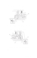
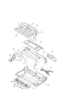
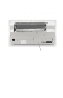
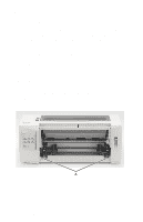
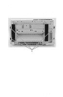
24xx Covers, Top Removal 1. Turn the printer off and disconnect the power cord at the printer. 2. Remove the tractor assembly, if it is installed in the pull tractor position, by pressing the locking levers and pulling the tractor assembly out of the printer. 3. Remove the ribbon access cover. Go to "Covers, Ribbon Access Removal" on page 4-6. 4. Remove the front cover. Go to "Covers, Front Removal" on page 4-6. 5. Remove the option cover. Go to "Covers, Option Removal" on page 4-7. Note: With the option cover removed, you can see the operator panel cable attached to the logic board. 6. Disconnect the operator panel cable from the logic board. 7. Remove the two screws [A] from each side of the front cover area. 4-8 Service Manual
-
 1
1 -
2
-
3
-
4
-
5
-
6
-
7
-
8
-
9
-
10
-
11
-
12
-
13
-
14
-
15
-
16
-
17
-
18
-
19
-
20
-
21
-
22
-
23
-
24
-
25
-
26
-
27
-
28
-
29
-
30
-
31
-
32
-
33
-
34
-
35
-
36
-
37
-
38
-
39
-
40
-
41
-
42
-
43
-
44
-
45
-
46
-
47
-
48
-
49
-
50
-
51
-
52
-
53
-
54
-
55
-
56
-
57
-
58
-
59
-
60
-
61
-
62
-
 63
63 -
 64
64 -
 65
65 -
 66
66 -
 67
67 -
 68
68 -
 69
69 -
 70
70 -
 71
71 -
 72
72 -
 73
73 -
74
-
75
-
76
-
77
-
78
-
79
-
80
-
81
-
82
-
83
-
84
-
85
-
86
-
87
-
88
-
89
-
90
-
91
-
92
-
93
-
94
-
95
-
96
-
97
-
98
-
99
-
100
-
101
-
102
-
103
-
104
-
105
-
106
-
107
-
108
-
109
-
110
-
111
-
112
-
113
-
114
-
115
-
116
-
117
-
118
-
119
-
120
-
121
-
122
-
123
-
124
-
125
-
126
-
127
-
128
-
129
-
130
-
131
-
132
-
133
-
134
-
135
-
136
-
137
-
138
-
139
-
140
-
141
-
142
-
143
-
144
-
145
-
146
-
147
-
148
-
149
-
150
-
151
-
152
-
153
-
154
-
155
-
156
-
157
-
158
-
159
-
160
-
161
-
162
-
163
-
164
-
165
-
166
-
167
-
168
-
169
-
170
 |
 |

4-8
Service Manual
24xx
Covers, Top Removal
1.
Turn the printer off and disconnect the power cord at the printer.
2.
Remove the tractor assembly, if it is installed in the pull tractor
position, by pressing the locking levers and pulling the tractor
assembly out of the printer.
3.
Remove the ribbon access cover. Go to
“Covers, Ribbon
Access Removal” on page 4-6
.
4.
Remove the front cover. Go to
“Covers, Front Removal” on
page 4-6
.
5.
Remove the option cover. Go to
“Covers, Option Removal” on
page 4-7
.
Note:
With the option cover removed, you can see the operator
panel cable attached to the logic board.
6.
Disconnect the operator panel cable from the logic board.
7.
Remove the two screws [
A
] from each side of the front cover
area.