Lexmark Forms Printer 2400 Service Manual - Page 64
Bidirectional Print Adjustment, Pitch, Micro, Set TOF
 |
View all Lexmark Forms Printer 2400 manuals
Add to My Manuals
Save this manual to your list of manuals |
Page 64 highlights
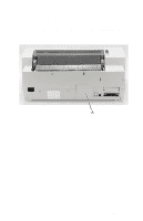
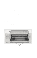
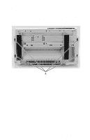
24xx Note: For maximum print quality, adjust the head gap on both the left and right sides of the printer to within +/- 0.01mm. If the gap value exceeds the specified range, return to step 4 and re-adjust both left and right gap adjust bushings. 11. After confirming the head gap is within the specified range for all (left, right and center) printhead positions, apply Lock Tite on both bushings. Bidirectional Print Adjustment After replacing any mechanical part which affects the operation of the logic board or the carrier, perform the following procedure to adjust the bidirectional print. This adjustment cannot be completed if the printer runs out of paper, so be sure to use continuous forms. 1. Through the Setup Menu, be sure the Default Macro is set to Disabled. 2. Turn the printer off. 3. Open the operator panel cover to access layer two. 4. Press and hold the Pitch key, while turning the printer on. - The draft alignment bars print. - The current value is the number printed below the bars. 5. To set Draft, select the best alignment from the alignment bars in rows 01 - 11. 6. Press Micro↑ or Micro ↓ to select the best alignment by number, or keep the current value. After selecting, the printer prints a single row showing the current alignment setting. 7. Press Set TOF to save the selection. - The printer automatically prints the alignment bars for NLQ. - The current value is the number printed below the bars. 8. To set NLQ, select the best alignment from the alignment bars in rows 01 - 11. The current value is the number printed below the bar. 9. Press Micro↑ or Micro ↓ to select the best alignment by number, or keep the current value. After selecting, the printer prints a single row showing the current alignment setting. 10. Press Set TOF to save the selection. 11. Close the operator panel cover. The printer returns to Ready. 4-4 Service Manual
-
 1
1 -
2
-
3
-
4
-
5
-
6
-
7
-
8
-
9
-
10
-
11
-
12
-
13
-
14
-
15
-
16
-
17
-
18
-
19
-
20
-
21
-
22
-
23
-
24
-
25
-
26
-
27
-
28
-
29
-
30
-
31
-
32
-
33
-
34
-
35
-
36
-
37
-
38
-
39
-
40
-
41
-
42
-
43
-
44
-
45
-
46
-
47
-
48
-
49
-
50
-
51
-
52
-
53
-
54
-
55
-
56
-
57
-
58
-
 59
59 -
 60
60 -
 61
61 -
 62
62 -
 63
63 -
 64
64 -
 65
65 -
 66
66 -
 67
67 -
 68
68 -
 69
69 -
70
-
71
-
72
-
73
-
74
-
75
-
76
-
77
-
78
-
79
-
80
-
81
-
82
-
83
-
84
-
85
-
86
-
87
-
88
-
89
-
90
-
91
-
92
-
93
-
94
-
95
-
96
-
97
-
98
-
99
-
100
-
101
-
102
-
103
-
104
-
105
-
106
-
107
-
108
-
109
-
110
-
111
-
112
-
113
-
114
-
115
-
116
-
117
-
118
-
119
-
120
-
121
-
122
-
123
-
124
-
125
-
126
-
127
-
128
-
129
-
130
-
131
-
132
-
133
-
134
-
135
-
136
-
137
-
138
-
139
-
140
-
141
-
142
-
143
-
144
-
145
-
146
-
147
-
148
-
149
-
150
-
151
-
152
-
153
-
154
-
155
-
156
-
157
-
158
-
159
-
160
-
161
-
162
-
163
-
164
-
165
-
166
-
167
-
168
-
169
-
170
 |
 |