Lexmark Forms Printer 2400 Service Manual - Page 70
cable is correctly aligned and inserted securely into the logic board.
 |
View all Lexmark Forms Printer 2400 manuals
Add to My Manuals
Save this manual to your list of manuals |
Page 70 highlights
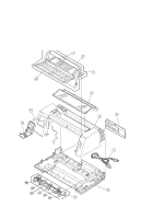
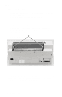
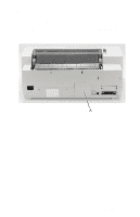
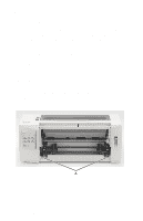
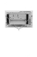
24xx 10. Turn the printer right side up and insert a flat blade screwdriver into each of the two holes [A] in the back of the top cover. 11. Lift the top cover up and over the print unit assembly. Note: When replacing the top cover, be sure the operator panel cable is correctly aligned and inserted securely into the logic board. Damage to the operator panel cable may cause failure of other electrical components in the printer. 4-10 Service Manual
-
 1
1 -
2
-
3
-
4
-
5
-
6
-
7
-
8
-
9
-
10
-
11
-
12
-
13
-
14
-
15
-
16
-
17
-
18
-
19
-
20
-
21
-
22
-
23
-
24
-
25
-
26
-
27
-
28
-
29
-
30
-
31
-
32
-
33
-
34
-
35
-
36
-
37
-
38
-
39
-
40
-
41
-
42
-
43
-
44
-
45
-
46
-
47
-
48
-
49
-
50
-
51
-
52
-
53
-
54
-
55
-
56
-
57
-
58
-
59
-
60
-
61
-
62
-
63
-
64
-
 65
65 -
 66
66 -
 67
67 -
 68
68 -
 69
69 -
 70
70 -
 71
71 -
 72
72 -
 73
73 -
 74
74 -
 75
75 -
76
-
77
-
78
-
79
-
80
-
81
-
82
-
83
-
84
-
85
-
86
-
87
-
88
-
89
-
90
-
91
-
92
-
93
-
94
-
95
-
96
-
97
-
98
-
99
-
100
-
101
-
102
-
103
-
104
-
105
-
106
-
107
-
108
-
109
-
110
-
111
-
112
-
113
-
114
-
115
-
116
-
117
-
118
-
119
-
120
-
121
-
122
-
123
-
124
-
125
-
126
-
127
-
128
-
129
-
130
-
131
-
132
-
133
-
134
-
135
-
136
-
137
-
138
-
139
-
140
-
141
-
142
-
143
-
144
-
145
-
146
-
147
-
148
-
149
-
150
-
151
-
152
-
153
-
154
-
155
-
156
-
157
-
158
-
159
-
160
-
161
-
162
-
163
-
164
-
165
-
166
-
167
-
168
-
169
-
170
 |
 |

4-10
Service Manual
24xx
10.
Turn the printer right side up and insert a flat blade screwdriver
into each of the two holes [
A
] in the back of the top cover.
11.
Lift the top cover up and over the print unit assembly.
Note:
When replacing the top cover, be sure the operator panel
cable is correctly aligned and inserted securely into the logic board.
Damage to the operator panel cable may cause failure of other
electrical components in the printer.