NEC M40-2-AV M40/46-2 user's manual - Page 15
Terminal Panel - multeos
 |
UPC - 805736024913
View all NEC M40-2-AV manuals
Add to My Manuals
Save this manual to your list of manuals |
Page 15 highlights
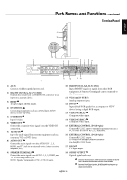
- English Part Names and Functions - continued Terminal Panel 17 18 IN OUT 1 AC IN 15 16 2 RGB/HV OUT R G B H V R G B H V RGB/HV IN 10 3 4 6 5 7 89 HDMI DVD/HD IN VIDEO Y Cb/Pb Cr/Pr S-VIDEO IN OUT R AUDIO AUDIO OUT R VGA(D-SUB) DVI(DVI-D) PC IN L L IN AUDIO3 IN AUDIO2 IN AUDIO1 IN IN SPEAKER RL - - 11 12 13 14 1) AC IN Connects with the supplied power cord. 2) RGB/HV OUT [R, G, B, H, V] (BNC) Outputs the signal from the RGB/HV IN connector to an input on a separate device. 3) HDMI To input digital HDMI signals. 4) DVD/HD IN Connecting equipment such as a DVD player, HDTV device, or Set-Top-Box. 5) S-VIDEO IN Input S-video. 6) VIDEO OUT Output the composite video signal from the VIDEO IN connection. 7) AUDIO IN Input the audio signal from external equipment such as a computer, VCR or DVD player. 8) AUDIO OUT Output the audio signal from the AUDIO IN 1, 2, 3, HDMI, and TV jack to an external device (stereo receiver, amplifier, etc,). 10) RGB/HV IN [R, G, B, H, V] (BNC) Input RGB/HV signals or signals from other RGB equipment. A Sync-on-Green signal can be connected to the G connector. 11) VGA (mini D-SUB15) Analog computer input. 12) DVI-D Input digital RGB signals from a computer or HDTV device having a digital RGB output. 13) VIDEO IN (RCA) Composite video input. 14) VIDEO IN (BNC) Composite video input. 15) EXTERNAL CONTROL (D-Sub 9 pin) Connect RS-232C input to external equipment such as a PC in order to control RS-232C functions. 16) EXTERNAL CONTROL (D-Sub 9 pin) Connect RS-232C output. To connect to multiple Multeos monitors via daisy RS-232C Chain. 17) RF IN TV signal input. 9) SPEAKER TERMINALS Output the audio signal from AUDIO 1, 2, 3, HDMI, and TV to external speakers jack. NOTE: Speaker Terminal for 15W + 15W (8 ohm). 18) S/PDIF OUTPUT Optical digital audio out. Denotes AV unit function. All AV functions are enabled with the AV unit is installed. Not all models have the AV unit installed. Denotes Digital Tuner function. All DTV and AV functions are enabled when the DTV unit is installed. Not all models will have the digital tuner installed. English-11
-
 1
1 -
2
-
3
-
4
-
5
-
6
-
7
-
8
-
9
-
 10
10 -
 11
11 -
 12
12 -
 13
13 -
 14
14 -
 15
15 -
 16
16 -
 17
17 -
 18
18 -
 19
19 -
 20
20 -
21
-
22
-
23
-
24
-
25
-
26
-
27
-
28
-
29
-
30
-
31
-
32
-
33
-
34
-
35
-
36
-
37
-
38
-
39
-
40
-
41
-
42
-
43
-
44
-
45
-
46
-
47
-
48
-
49
-
50
-
51
-
52
-
53
-
54
-
55
-
56
-
57
-
58
-
59
-
60
-
61
-
62
-
63
-
64
-
65
-
66
-
67
-
68
-
69
-
70
-
71
-
72
-
73
-
74
-
75
-
76
-
77
-
78
-
79
-
80
-
81
-
82
-
83
-
84
-
85
-
86
-
87
-
88
-
89
-
90
-
91
-
92
-
93
-
94
-
95
-
96
-
97
-
98
-
99
-
100
-
101
-
102
-
103
-
104
-
105
-
106
-
107
-
108
-
109
-
110
-
111
-
112
-
113
-
114
-
115
-
116
-
117
-
118
-
119
-
120
-
121
-
122
-
123
-
124
-
125
-
126
-
127
-
128
-
129
-
130
-
131
-
132
-
133
-
134
-
135
-
136
-
137
-
138
-
139
-
140
-
141
-
142
-
143
-
144
-
145
-
146
-
147
-
148
-
149
-
150
-
151
-
152
 |
 |
