Netgear XM128 QIG - Quick Install Guide - Page 110
Table C-2, Table C-3
 |
View all Netgear XM128 manuals
Add to My Manuals
Save this manual to your list of manuals |
Page 110 highlights
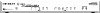
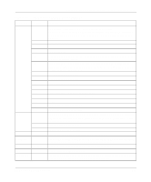
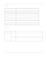
Reference Guide for the Model XM128 ISDN Digital Modem Table C-2 shows the outputs for the AT13 commands. Table C-2. ATI3 command output Output parameter Connect DTE Speed Error Control Level Protocol Link Speed Octets Received Octets Sent Cause Cause Value HDLC FCS Error HDLC Transmit Under-run HDLC Receive Over-run Output value description Current online DTE speed Error control protocol used for current session Current online DCE speed, line speed Number of data octets received from remote Number of data octets sent to remote Verbose disconnection reason for the last session Numerical disconnection reason for the last session Errors in frame (block) checksum (If there were many FCS Errors, you may have experienced problems on the line.) For processor power measurement of the Model XM128 modem For processor power measurement of the Model XM128 modem Table C-3 lists the extended AT& command set. Table C-3. Command &Cn Extended AT& command set Options &C0 &C1 * Function and description Carrier Detect (CD) options. See also S-register 21.4. For a description of Extended S-registers, refer to Table D-4 on page D-5 in Appendix D, "Status Registers and Result Codes." CD is always on. See also S-register S42.7. CD tracks presence of carrier. See also S38.3 and S42.7. For a description of Extended S-registers, refer to Table D-4 on page D-5 in Appendix D, "Status Registers and Result Codes." C-8 AT Command Set Reference
-
 1
1 -
2
-
3
-
4
-
5
-
6
-
7
-
8
-
9
-
10
-
11
-
12
-
13
-
14
-
15
-
16
-
17
-
18
-
19
-
20
-
21
-
22
-
23
-
24
-
25
-
26
-
27
-
28
-
29
-
30
-
31
-
32
-
33
-
34
-
35
-
36
-
37
-
38
-
39
-
40
-
41
-
42
-
43
-
44
-
45
-
46
-
47
-
48
-
49
-
50
-
51
-
52
-
53
-
54
-
55
-
56
-
57
-
58
-
59
-
60
-
61
-
62
-
63
-
64
-
65
-
66
-
67
-
68
-
69
-
70
-
71
-
72
-
73
-
74
-
75
-
76
-
77
-
78
-
79
-
80
-
81
-
82
-
83
-
84
-
85
-
86
-
87
-
88
-
89
-
90
-
91
-
92
-
93
-
94
-
95
-
96
-
97
-
98
-
99
-
100
-
101
-
102
-
103
-
104
-
 105
105 -
 106
106 -
 107
107 -
 108
108 -
 109
109 -
 110
110 -
 111
111 -
 112
112 -
 113
113 -
 114
114 -
 115
115 -
116
-
117
-
118
-
119
-
120
-
121
-
122
-
123
-
124
-
125
-
126
-
127
-
128
-
129
-
130
-
131
-
132
-
133
-
134
-
135
-
136
-
137
-
138
-
139
-
140
-
141
-
142
-
143
-
144
-
145
-
146
-
147
-
148
-
149
-
150
-
151
-
152
-
153
-
154
-
155
-
156
 |
 |