Netgear XM128 QIG - Quick Install Guide - Page 31
Verifying Hardware Installation
 |
View all Netgear XM128 manuals
Add to My Manuals
Save this manual to your list of manuals |
Page 31 highlights
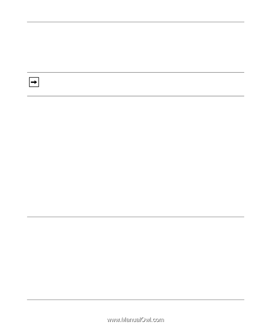
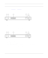
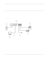
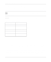
Reference Guide for the Model XM128 ISDN Digital Modem To install your Model XM128 modem, follow these steps: 1. Connect the male end of the 25-pin cable to the RS-232 COM port of the Model XM128 modem. 2. Connect the other end of the 25-pin cable (female end) to the serial (COM) port on your computer. Note: If your computer has a 9-pin serial connector, use a 25-pin to 9-pin converter (25-pin male to 9-pin female). If you have a Macintosh, a special cable is needed for the connection. 3. Using the ISDN cable that is included, connect the RJ-45 connector on one end of the cable to the ISDN port on the back of the Model XM128 modem. 4. For European models, connect the other end of the RJ-45 ISDN cable to your NT-1 terminal or S/T interface. Using the proper cable supplied with your NT-1, connect your NT-1 or U interface to the wall jack installed by your phone company. 5. For North American models, connect the other end of the RJ-45 ISDN cable to the wall jack installed by your phone company. 6. Using the proper cable, insert the round end of the power adapter in the POWER connector on the rear panel. 7. Plug the power supply unit into an AC wall outlet. 8. Turn the power on to your Model XM128 modem. 9. Turn the power on to your computer. Verifying Hardware Installation When the installation is complete and power applied to the modem, a self-test sequence begins. The B1, B2, and AA LED lights blink on and then off again. After this cycle is complete, the PWR (power) LED remains on. If the test routine fails, the D LED blinks. Refer to Chapter 10, "Troubleshooting," for more information about the self-test and the error codes. Installation 2-3
-
 1
1 -
2
-
3
-
4
-
5
-
6
-
7
-
8
-
9
-
10
-
11
-
12
-
13
-
14
-
15
-
16
-
17
-
18
-
19
-
20
-
21
-
22
-
23
-
24
-
25
-
 26
26 -
 27
27 -
 28
28 -
 29
29 -
 30
30 -
 31
31 -
 32
32 -
 33
33 -
 34
34 -
 35
35 -
 36
36 -
37
-
38
-
39
-
40
-
41
-
42
-
43
-
44
-
45
-
46
-
47
-
48
-
49
-
50
-
51
-
52
-
53
-
54
-
55
-
56
-
57
-
58
-
59
-
60
-
61
-
62
-
63
-
64
-
65
-
66
-
67
-
68
-
69
-
70
-
71
-
72
-
73
-
74
-
75
-
76
-
77
-
78
-
79
-
80
-
81
-
82
-
83
-
84
-
85
-
86
-
87
-
88
-
89
-
90
-
91
-
92
-
93
-
94
-
95
-
96
-
97
-
98
-
99
-
100
-
101
-
102
-
103
-
104
-
105
-
106
-
107
-
108
-
109
-
110
-
111
-
112
-
113
-
114
-
115
-
116
-
117
-
118
-
119
-
120
-
121
-
122
-
123
-
124
-
125
-
126
-
127
-
128
-
129
-
130
-
131
-
132
-
133
-
134
-
135
-
136
-
137
-
138
-
139
-
140
-
141
-
142
-
143
-
144
-
145
-
146
-
147
-
148
-
149
-
150
-
151
-
152
-
153
-
154
-
155
-
156
 |
 |