Netgear XM128 QIG - Quick Install Guide - Page 143
Appendix F, Serial Port Interface
 |
View all Netgear XM128 manuals
Add to My Manuals
Save this manual to your list of manuals |
Page 143 highlights
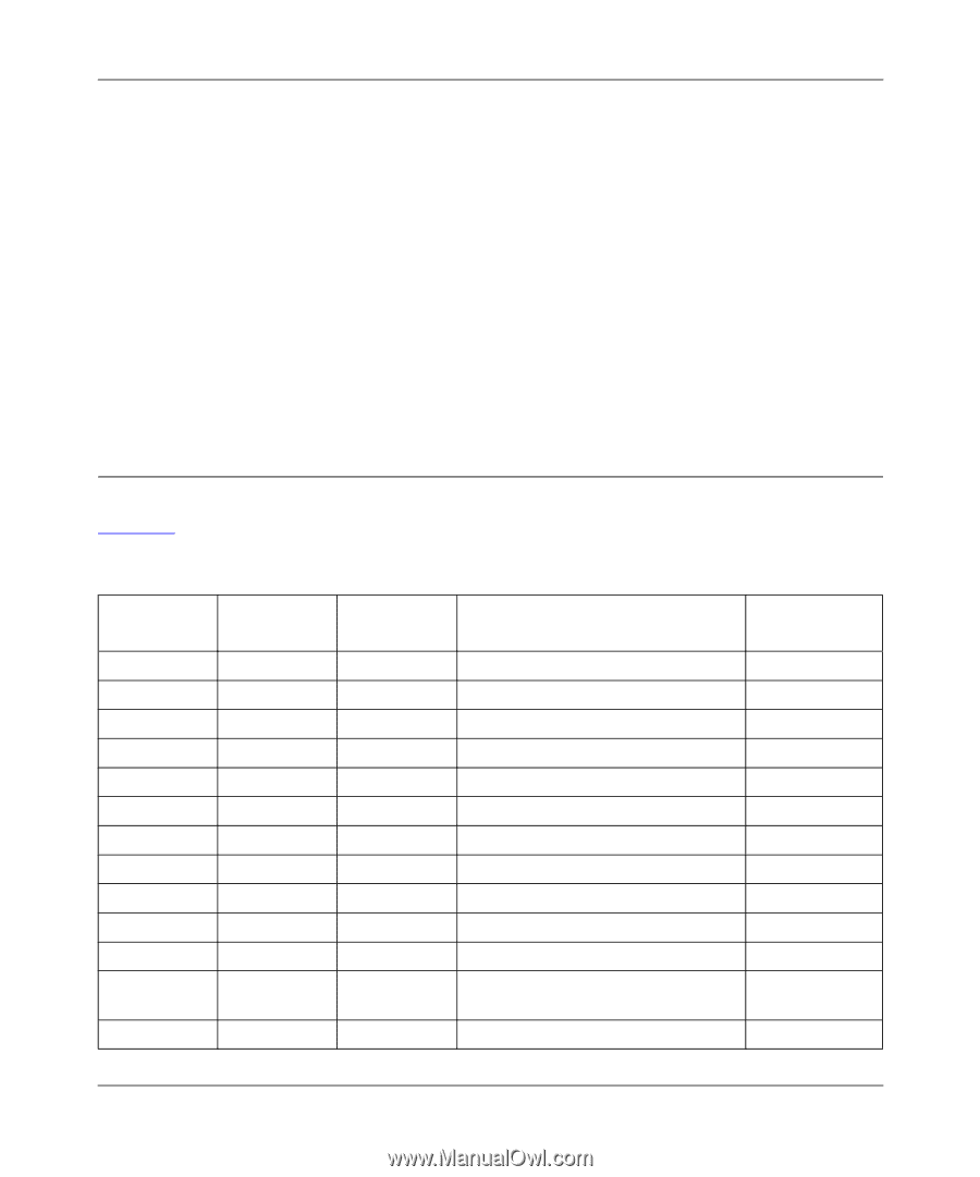
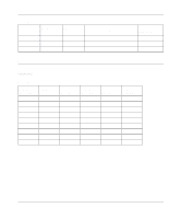
Appendix F Serial Port Interface This appendix provides information about the serial port interface for the Model XM128 ISDN Digital Modem. RS-232 Serial Interface Table F-1 describes the RS-232 25-pin serial port interface for the Model XM128 modem. Table F-1. Pin number 1 2 3 4 5 6 7 8 15 17 18 20 21 Serial port interface ITU-TSS signal name 101 103 104 105 106 107 102 109 114 115 141 108/2108/1 140 EIA signal name AA BA BB CA CB CC AB CF DB DD CD Signal/pin description Protective ground (GND). Transmitted data (TXD). Received data (RXD). Request to send (RTS). Clear to send (CTS). Data set ready (DSR). Signal ground (GND). Data carrier detected (DCD). Transmit clock signal (source: DCE). Synchronous receive clock. Local analog loopback test. Data terminal ready (DTR). Connect DCE to line. Remote digital loop test. Signal direction DTE -DCE ? Serial Port Interface F-1
-
 1
1 -
2
-
3
-
4
-
5
-
6
-
7
-
8
-
9
-
10
-
11
-
12
-
13
-
14
-
15
-
16
-
17
-
18
-
19
-
20
-
21
-
22
-
23
-
24
-
25
-
26
-
27
-
28
-
29
-
30
-
31
-
32
-
33
-
34
-
35
-
36
-
37
-
38
-
39
-
40
-
41
-
42
-
43
-
44
-
45
-
46
-
47
-
48
-
49
-
50
-
51
-
52
-
53
-
54
-
55
-
56
-
57
-
58
-
59
-
60
-
61
-
62
-
63
-
64
-
65
-
66
-
67
-
68
-
69
-
70
-
71
-
72
-
73
-
74
-
75
-
76
-
77
-
78
-
79
-
80
-
81
-
82
-
83
-
84
-
85
-
86
-
87
-
88
-
89
-
90
-
91
-
92
-
93
-
94
-
95
-
96
-
97
-
98
-
99
-
100
-
101
-
102
-
103
-
104
-
105
-
106
-
107
-
108
-
109
-
110
-
111
-
112
-
113
-
114
-
115
-
116
-
117
-
118
-
119
-
120
-
121
-
122
-
123
-
124
-
125
-
126
-
127
-
128
-
129
-
130
-
131
-
132
-
133
-
134
-
135
-
136
-
137
-
 138
138 -
 139
139 -
 140
140 -
 141
141 -
 142
142 -
 143
143 -
 144
144 -
 145
145 -
 146
146 -
 147
147 -
 148
148 -
149
-
150
-
151
-
152
-
153
-
154
-
155
-
156
 |
 |