Netgear XM128 QIG - Quick Install Guide - Page 23
Front Panel
 |
View all Netgear XM128 manuals
Add to My Manuals
Save this manual to your list of manuals |
Page 23 highlights
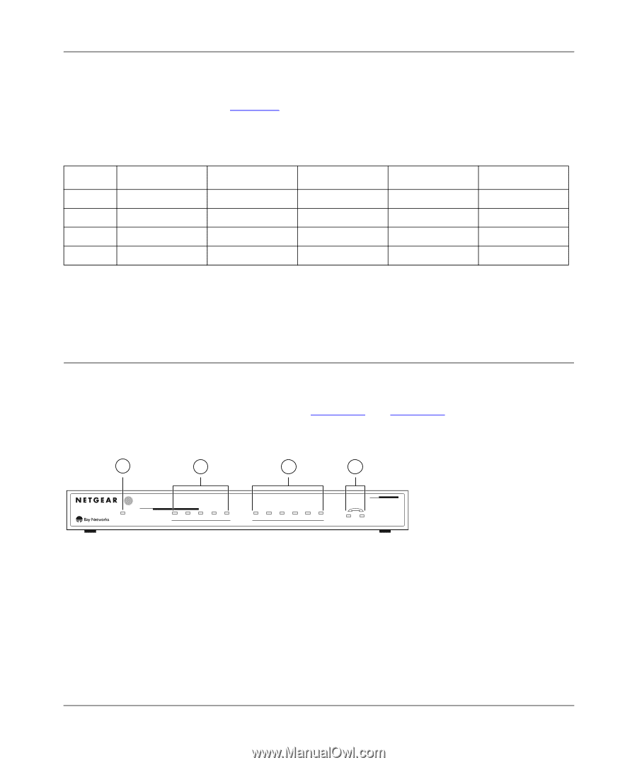
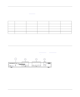
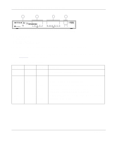
Reference Guide for the Model XM128 ISDN Digital Modem Interface Options Several interfaces are available. Table 1-1 lists the interface options for the Model XM128 modem as applicable for each region. Table 1-1. Interface options XM128NA XM128GE Unit XM128U XM128S Region North America Germany Interface U (internal NT-1) S/T Auto SPID Switch XM128UK XM128S UK S/T XM128AU XM128S Australia S/T XM128JP XM128D Japan Internal DSU For the North American ISDN, NETGEAR provides an optional 2B1Q U interface to allow direct connection to the network without the use of an external NT-1 device. Front Panel For easier management and control of the Model XM128 modem, familiarize yourself with the components on the front panel, as illustrated in Figure 1-1 and Figure 1-2. Use the key at the bottom of each illustration to identify the panel components. 1 2 3 4 S INTERFACE 128Kpbs ISDN Digital Modem PWR D B1 B2 AA CP ISDN DTR DSR RTS CTS TD RD COM MODELXM128 1 2 Key: 1 = PWR (power) LED 2 = ISDN LEDs 3 = RS-232 COM LEDs 4 = PHONE 1 and PHONE 2 LEDs 7848MEA Figure 1-1. Front panel of the Model XM128 modem (with S/T interface) Introduction 1-3
-
 1
1 -
2
-
3
-
4
-
5
-
6
-
7
-
8
-
9
-
10
-
11
-
12
-
13
-
14
-
15
-
16
-
17
-
 18
18 -
 19
19 -
 20
20 -
 21
21 -
 22
22 -
 23
23 -
 24
24 -
 25
25 -
 26
26 -
 27
27 -
 28
28 -
29
-
30
-
31
-
32
-
33
-
34
-
35
-
36
-
37
-
38
-
39
-
40
-
41
-
42
-
43
-
44
-
45
-
46
-
47
-
48
-
49
-
50
-
51
-
52
-
53
-
54
-
55
-
56
-
57
-
58
-
59
-
60
-
61
-
62
-
63
-
64
-
65
-
66
-
67
-
68
-
69
-
70
-
71
-
72
-
73
-
74
-
75
-
76
-
77
-
78
-
79
-
80
-
81
-
82
-
83
-
84
-
85
-
86
-
87
-
88
-
89
-
90
-
91
-
92
-
93
-
94
-
95
-
96
-
97
-
98
-
99
-
100
-
101
-
102
-
103
-
104
-
105
-
106
-
107
-
108
-
109
-
110
-
111
-
112
-
113
-
114
-
115
-
116
-
117
-
118
-
119
-
120
-
121
-
122
-
123
-
124
-
125
-
126
-
127
-
128
-
129
-
130
-
131
-
132
-
133
-
134
-
135
-
136
-
137
-
138
-
139
-
140
-
141
-
142
-
143
-
144
-
145
-
146
-
147
-
148
-
149
-
150
-
151
-
152
-
153
-
154
-
155
-
156
 |
 |