Netgear XM128 QIG - Quick Install Guide - Page 94
Analyzing the Captured Data
 |
View all Netgear XM128 manuals
Add to My Manuals
Save this manual to your list of manuals |
Page 94 highlights
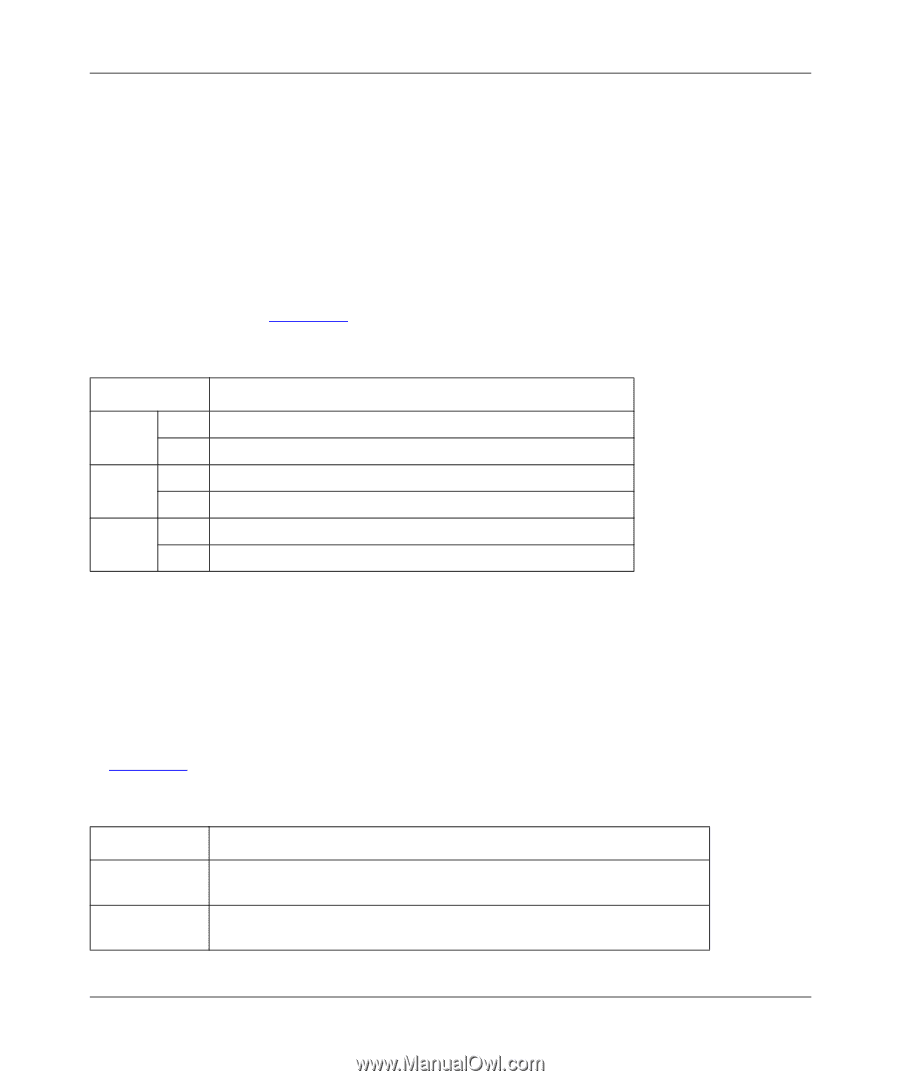
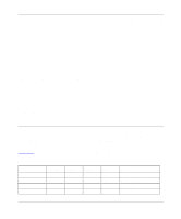
Reference Guide for the Model XM128 ISDN Digital Modem The DTE-DCE protocols (at the R reference point according to the ISDN nomenclature) include the AT commands/responses as well as the CAPI internal interface. The CAPI internal interface is used with NETGEAR CAPI driver. The NETGEAR CAPI driver communicates with the Model XM128 modem through this internal interface. It is not recommended that users get involved in this internal interface. The AT commands/responses, on the other hand, are in a standard user interface. An analysis of these commands and responses might prove very informative. All messages captured by the EPA are tagged with a time stamp according to a free running timer that starts at the beginning of data capture. The resolution of this timing information is in 0.01 second. The commands listed in Table 10-2 determine the kind of protocol data to be captured by the EPA. Table 10-2. EPA Commands AT Command Description ATCDn n = 0 Disables the capture of D channel protocols n = 1 Enables the capture of D channel protocols (default) ATCBn n = 0 Disables the capture of B channel protocols (default) ATCCn n = 1 n = 0 n = 1 Enables the capture of B channel protocols Disables the capture of DTE-DCE interface protocols (default) Enables the capture of DTE-DCE interface protocols The EPA starts to capture data when the command ATCT is issued. This capturing process continues until the command ATC$ is issued. The EPA maintains 8 Kbytes RAM as a ring buffer. In case the buffer is full, the earliest data captured is overwritten by the latest data. Analyzing the Captured Data To view the analyzed result, use the command ATC$. The relevant AT commands are summarized in Table 10-3. Table 10-3. Commands for analyzing captured data AT Command ATCT ATC$ Description Clears buffer and starts the embedded protocol analyzer. Captures data immediately and starts the timer. Invokes the interpretation function of the embedded protocol analyzer and displays the results on the DTE screen. 10-6 Troubleshooting
-
 1
1 -
2
-
3
-
4
-
5
-
6
-
7
-
8
-
9
-
10
-
11
-
12
-
13
-
14
-
15
-
16
-
17
-
18
-
19
-
20
-
21
-
22
-
23
-
24
-
25
-
26
-
27
-
28
-
29
-
30
-
31
-
32
-
33
-
34
-
35
-
36
-
37
-
38
-
39
-
40
-
41
-
42
-
43
-
44
-
45
-
46
-
47
-
48
-
49
-
50
-
51
-
52
-
53
-
54
-
55
-
56
-
57
-
58
-
59
-
60
-
61
-
62
-
63
-
64
-
65
-
66
-
67
-
68
-
69
-
70
-
71
-
72
-
73
-
74
-
75
-
76
-
77
-
78
-
79
-
80
-
81
-
82
-
83
-
84
-
85
-
86
-
87
-
88
-
 89
89 -
 90
90 -
 91
91 -
 92
92 -
 93
93 -
 94
94 -
 95
95 -
 96
96 -
 97
97 -
 98
98 -
 99
99 -
100
-
101
-
102
-
103
-
104
-
105
-
106
-
107
-
108
-
109
-
110
-
111
-
112
-
113
-
114
-
115
-
116
-
117
-
118
-
119
-
120
-
121
-
122
-
123
-
124
-
125
-
126
-
127
-
128
-
129
-
130
-
131
-
132
-
133
-
134
-
135
-
136
-
137
-
138
-
139
-
140
-
141
-
142
-
143
-
144
-
145
-
146
-
147
-
148
-
149
-
150
-
151
-
152
-
153
-
154
-
155
-
156
 |
 |