Netgear XM128 QIG - Quick Install Guide - Page 122
Command, Decimal, Hexadecimal, Function and, description, Default or, reference
 |
View all Netgear XM128 manuals
Add to My Manuals
Save this manual to your list of manuals |
Page 122 highlights
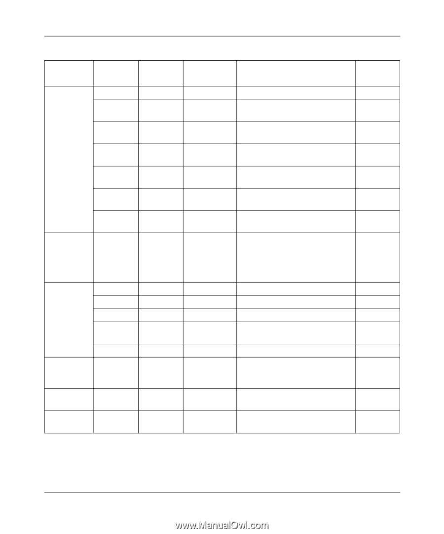
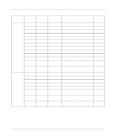
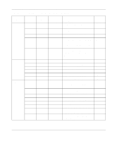
Reference Guide for the Model XM128 ISDN Digital Modem Table D-4. Extended S-registers ATSn=x (continued) Command Bit S24= 0-1 2 3 5-4 S25= S27= 3-5 S29= S31= S32= Decimal 0-3 0 4 0 8 0-255 0 24 32 40 039 0-255 0-255 Hexadecimal Function and description Default or reference Bitmapped register. 0-3 Ring volume control, in increments N0-3 of 1 in decimal value 0 4 0 8 0-FF Ignore S21.1-2 when PHONE 1 keypad is dialed. Do not ignore S21-2 when PHONE 1 keypad is dialed. Ignore S21.1-2 when PHONE 2 keypad is dialed. Do not ignore S21-2 when PHONE 2 keypad is dialed. Speaker volume control, in L0-3 increments of 16 in decimal value Specify the time delay that DTR signal needs to be off before it is recognized, in 10 ms units. If S25=0, the delay time is set to 4 ms. +000 0 18 20 28 039 0-FF 0-FF Bitmapped register Flow control is disabled. &H0 Hardware (RTS/CTS) flow control. &H3 Software (XON/XOFF) flow &H4 control. Reserved. &H5 Sets default dial PHONE number pointer; uses AT&Zn=s to store PHONE numbers. +000 *D Holds the ASCII decimal value of +017 the XON. Holds the ASCII decimal value of +019 the XOFF. D-8 Status Registers and Result Codes
-
 1
1 -
2
-
3
-
4
-
5
-
6
-
7
-
8
-
9
-
10
-
11
-
12
-
13
-
14
-
15
-
16
-
17
-
18
-
19
-
20
-
21
-
22
-
23
-
24
-
25
-
26
-
27
-
28
-
29
-
30
-
31
-
32
-
33
-
34
-
35
-
36
-
37
-
38
-
39
-
40
-
41
-
42
-
43
-
44
-
45
-
46
-
47
-
48
-
49
-
50
-
51
-
52
-
53
-
54
-
55
-
56
-
57
-
58
-
59
-
60
-
61
-
62
-
63
-
64
-
65
-
66
-
67
-
68
-
69
-
70
-
71
-
72
-
73
-
74
-
75
-
76
-
77
-
78
-
79
-
80
-
81
-
82
-
83
-
84
-
85
-
86
-
87
-
88
-
89
-
90
-
91
-
92
-
93
-
94
-
95
-
96
-
97
-
98
-
99
-
100
-
101
-
102
-
103
-
104
-
105
-
106
-
107
-
108
-
109
-
110
-
111
-
112
-
113
-
114
-
115
-
116
-
 117
117 -
 118
118 -
 119
119 -
 120
120 -
 121
121 -
 122
122 -
 123
123 -
 124
124 -
 125
125 -
 126
126 -
 127
127 -
128
-
129
-
130
-
131
-
132
-
133
-
134
-
135
-
136
-
137
-
138
-
139
-
140
-
141
-
142
-
143
-
144
-
145
-
146
-
147
-
148
-
149
-
150
-
151
-
152
-
153
-
154
-
155
-
156
 |
 |