Optoma FHDQ130 FHDQ130 User Manual - Page 10
Component Placement
 |
View all Optoma FHDQ130 manuals
Add to My Manuals
Save this manual to your list of manuals |
Page 10 highlights
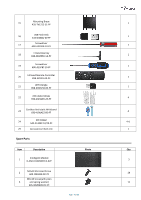
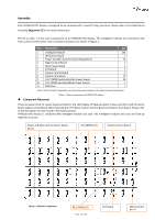
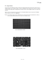
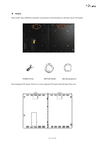
Assembly Each FHDQ130 LED display is designed to be mounted with a specific fixing structure. Please refer to the Mechanical Assembly (Appendix E) for the detail dimensions. The list in table 1 is the main components of an FHDQ130 LED display. The intelligent modules are mounted to the front surface and the other main component locations are shown in Figure 1. Item Description Qty 1 Intelligent Module 144 2 IR Receiver Board 1 3 Power and Mini Card Convertor Board(2in1) 72 4 Signal Control Board 1 5 Main Power Board 1 6 PV7 Board 1 7 System Control Board 1 8 System Core Board 72 9 4.2V /189W Switched Mode Power Supply 24 10 12V /200W Switched Mode Power Supply 1 11 EMI Filter 1 Note: The PSU output is adjustable, the actual value would subject to the label of manufacturing data Table 1 - Major components of FHDQ130 LED display ◆ Component Placement There are seven kinds of system board worked for the LED display, IR Receiver Board, Power and Mini Card Convertor Board, Signal Control Board, Main Power Board, PV7 Board ,System Control Board and System Core Board. Please refer to the description for each board in the follow sections. FHDQ130 LED display is combined with intelligent module and case. The intelligent modules and case are fixed by magnetic structure. Power and Mini Card Convertor Board (2in1) PSU 189W/4.2V System Control Board Figure 1 FHDQ130 Components PSU 200W/12V Page 10 of 64 PV7 Board Signal Control Board
-
 1
1 -
2
-
3
-
4
-
 5
5 -
 6
6 -
 7
7 -
 8
8 -
 9
9 -
 10
10 -
 11
11 -
 12
12 -
 13
13 -
 14
14 -
 15
15 -
16
-
17
-
18
-
19
-
20
-
21
-
22
-
23
-
24
-
25
-
26
-
27
-
28
-
29
-
30
-
31
-
32
-
33
-
34
-
35
-
36
-
37
-
38
-
39
-
40
-
41
-
42
-
43
-
44
-
45
-
46
-
47
-
48
-
49
-
50
-
51
-
52
-
53
-
54
-
55
-
56
-
57
-
58
-
59
-
60
-
61
-
62
-
63
-
64
 |
 |