Panasonic KX-P3696 Operating Instructions - Page 61
character.
 |
View all Panasonic KX-P3696 manuals
Add to My Manuals
Save this manual to your list of manuals |
Page 61 highlights
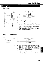
Printing Area Fanfold paper B O O OO I C O O Me\ 1st character O O O O O Printing area O O O O O O (-) O ,O A -O r. O O' Paper perforations :O A O O O O O O Printing area O O O O O O O O O D Push Pull A 1" (25.4 mm) B 0.7" (17.8 mm) C 0.33" (8.38 mm) 5.7" (144.8 mm) D 1" (25.4 mm) A: Value A indicates the area near the paper perforations where the quality may not be optimum. B: Value B indicates the minimum distance between the sprockets and first printable character. (When the left tractor is set on the left end and the margin is set to 0.) C: Value C indicates the area from the top edge of the paper to the top of the first printed character. D: Value D indicates the position where paper out is detected and printing may not be optimum. Single sheet and Envelope B IC B 1st character C Printing area D Single sheet and Envelope 1.5" (38 mm) 0.33" (8.38 mm) 1" (25.4 mm) B: Value B indicates the minimum distance between the edge of the paper and the first printable character. (When the left paper guide is set to the left end and the margin is set to 0.) C: Value C indicates the area from the top edge of the paper to the top of the first printed character. m D: Value D indicates the position where paper out is detected a and printing may not be optimum. (When printing on envelopes, do not print on area where edges overlap. Print quality may not be optimum.) 61
-
 1
1 -
2
-
3
-
4
-
5
-
6
-
7
-
8
-
9
-
10
-
11
-
12
-
13
-
14
-
15
-
16
-
17
-
18
-
19
-
20
-
21
-
22
-
23
-
24
-
25
-
26
-
27
-
28
-
29
-
30
-
31
-
32
-
33
-
34
-
35
-
36
-
37
-
38
-
39
-
40
-
41
-
42
-
43
-
44
-
45
-
46
-
47
-
48
-
49
-
50
-
51
-
52
-
53
-
54
-
55
-
 56
56 -
 57
57 -
 58
58 -
 59
59 -
 60
60 -
 61
61 -
 62
62 -
 63
63 -
 64
64 -
 65
65 -
 66
66 -
67
-
68
-
69
-
70
-
71
-
72
-
73
-
74
-
75
-
76
 |
 |
