Panasonic KX-P3696 Operating Instructions - Page 63
Connector, signals
 |
View all Panasonic KX-P3696 manuals
Add to My Manuals
Save this manual to your list of manuals |
Page 63 highlights
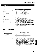
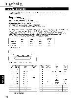
Connector pin signals STB...STROBE •This is a synchronizing input signal to read data into the printer. *This signal is normally high. Data is read in when it is low. DATA 1-DATA 8 *These are the input signals which carry the 8 data bits of information. • •The signal is read in synchronization with the STROBE pulse. A high level indicates a logical "1". ACK...ACKNOWLEDGE •This is an output signal to the computer indicating that the printer is ready to receive the next data. When the condition becomes true, the signal goes low. •The ACK signal is automatically sent whenever the printer is switched ON LINE and the BUSY signal drops from high to low. BUSY •This output signal indicates the status on which the printer cannot receive data. *The signal is high under the following conditions: 1. receive buffer full 2. printer is processing data 3. printer is OFF LINE 4. printer is in an error condition PO...PAPER OUT •This output signal indicates the absence of paper and goes high during a "Paper Out" condition. SLCT...SELECT *This output signal is high in the ON LINE mode and low when OFF LINE. •The printer enters the ON LINE mode: 1. when the printer is turned on 2. when PRIME is received 3. when the RESET command is received 4. when the ON LINE switch is pressed *The printer enters the OFF LINE mode: 1. when the printer is out of paper 2. when the printer is switched OFF LINE 0 AUTO FEED XT (AFXT) *While this input signal is low, one line feed (LF) command will be added to each carriage return (CR). 'Auto LF setting in the Function mode can alter the response by the printer to an AFXT signal. If auto LF is ON, the printer will perform a CR+ LF regardless of the level of the AFXT signal. When auto LF is OFF, automatic action is disabled. SG...SIGNAL GROUND •The twisted pair return wires (pins 19-30) are connected to signal ground. FG...FRAME GROUND • Frame ground is the same as chassis ground. +5 V *This is for evaluation only. It should not be used to supply power for external equipment. PRIME *This input signal is normally high and goes low to reset the printer. It can be received anytime during printer operation. ERROR 'This output signal is normally high, and goes low when an error occurs. An error condition can be caused by: 1. a "Paper Out" condition 2. the printer is OFF LINE 3. an overload condition exists SLCT IN *This input signal is normally low, and goes high when using the Setup Disk. Timing Chart (When normal printing code is received) DATA1 8 TB BUSY ACK T1 T2 T3 T5 T4 T1 0 5µs (Min) T2 0 5µs (Min) T3 0.5µs (Min) 74 5 ps (Max) T5 1 ms or less when buffer is not full Timing Diagram 63
-
 1
1 -
2
-
3
-
4
-
5
-
6
-
7
-
8
-
9
-
10
-
11
-
12
-
13
-
14
-
15
-
16
-
17
-
18
-
19
-
20
-
21
-
22
-
23
-
24
-
25
-
26
-
27
-
28
-
29
-
30
-
31
-
32
-
33
-
34
-
35
-
36
-
37
-
38
-
39
-
40
-
41
-
42
-
43
-
44
-
45
-
46
-
47
-
48
-
49
-
50
-
51
-
52
-
53
-
54
-
55
-
56
-
57
-
 58
58 -
 59
59 -
 60
60 -
 61
61 -
 62
62 -
 63
63 -
 64
64 -
 65
65 -
 66
66 -
 67
67 -
 68
68 -
69
-
70
-
71
-
72
-
73
-
74
-
75
-
76
 |
 |
