Sony HDR UX5 Instruction Manual - Page 118
Quick Reference, Identifying parts and controls, The Active Interface Shoe has a safety
 |
UPC - 027242701434
View all Sony HDR UX5 manuals
Add to My Manuals
Save this manual to your list of manuals |
Page 118 highlights
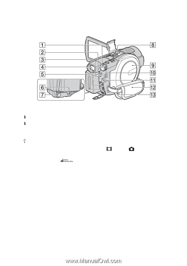
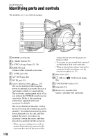
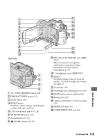
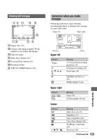
Quick Reference Identifying parts and controls The numbers in ( ) are reference pages. A POWER switch (24) B (flash) button (36) C /CHG (charge) lamp (21, 36) D REMOTE jack Connect other optional accessories. E (USB) jack (54) F A/V OUT jack (46) G DC IN jack (21) H Active Interface Shoe (35) The Active Interface Shoe supplies power to optional accessories such as a video light, a flash, or a microphone. The accessory can be turned on or off as you operate the POWER switch on your camcorder. Refer to the operating instructions supplied with your accessory for details. The Active Interface Shoe has a safety device for fixing the installed accessory securely. To connect an accessory, press down and push it to the end, and then tighten the screw. To remove an accessory, loosen the screw, and then press down and pull out the accessory. • When you are recording movies with an external flash (optional) connected to the accessory shoe, turn off the power of the 118 external flash to prevent charging noise being recorded. • You cannot use an external flash (optional) and the built-in flash at the same time. • When an external microphone (optional) is connected, it takes precedence over the internal microphone (p. 35). I Disc cover (27) J (Movie)/ (Still) mode lamps (24) K START/STOP button (34) L Grip belt (33) M Hooks for a shoulder belt Attach a shoulder belt (optional).
-
 1
1 -
2
-
3
-
4
-
5
-
6
-
7
-
8
-
9
-
10
-
11
-
12
-
13
-
14
-
15
-
16
-
17
-
18
-
19
-
20
-
21
-
22
-
23
-
24
-
25
-
26
-
27
-
28
-
29
-
30
-
31
-
32
-
33
-
34
-
35
-
36
-
37
-
38
-
39
-
40
-
41
-
42
-
43
-
44
-
45
-
46
-
47
-
48
-
49
-
50
-
51
-
52
-
53
-
54
-
55
-
56
-
57
-
58
-
59
-
60
-
61
-
62
-
63
-
64
-
65
-
66
-
67
-
68
-
69
-
70
-
71
-
72
-
73
-
74
-
75
-
76
-
77
-
78
-
79
-
80
-
81
-
82
-
83
-
84
-
85
-
86
-
87
-
88
-
89
-
90
-
91
-
92
-
93
-
94
-
95
-
96
-
97
-
98
-
99
-
100
-
101
-
102
-
103
-
104
-
105
-
106
-
107
-
108
-
109
-
110
-
111
-
112
-
 113
113 -
 114
114 -
 115
115 -
 116
116 -
 117
117 -
 118
118 -
 119
119 -
 120
120 -
 121
121 -
 122
122 -
 123
123 -
124
-
125
-
126
-
127
-
128
-
129
-
130
-
131
-
132
-
133
-
134
-
135
-
136
-
137
-
138
-
139
-
140
-
141
-
142
-
143
 |
 |