Stihl MS 311 User Manual - Page 23
Brake Lever
 |
View all Stihl MS 311 manuals
Add to My Manuals
Save this manual to your list of manuals |
Page 23 highlights
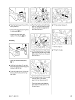
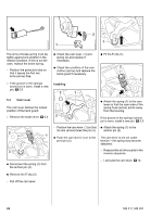
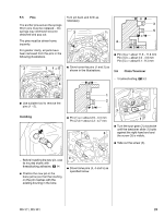
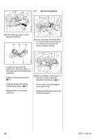
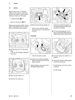
5.3 Brake Lever 1 1 4903RA029 TG 4903RA026 TG 4903RA027 TG : Insert the screws (arrows) and tighten them down firmly. - Fit the bumper strip. - Install the clutch drum, b 4.1 - Check operation, b 5.1 - Reassemble all other parts in the reverse sequence. - Troubleshooting, b 3 - Remove the brake band, b 5.2 - Engage the chain brake. The brake spring is now relaxed. : Use the assembly tool 1117 890 0900 to disconnect the brake spring (1) from the anchor pin (arrow). - Remove the brake spring from the brake lever. : Remove the E-clip (1). 1 2 : Lift and turn the strap (1) slightly, push it towards the hole (arrow) and remove it. : Remove the spacer sleeve (2) from the brake lever. 4903RA030 TG 2 1 4903RA119 TG 4903RA031 TG - Remove the shroud, b 6.4 : Take out the screws (arrows). - Remove the sleeve (1). - Lift the hand guard a little and remove the fan housing. : Pull the hand guard (1) and brake lever (2) off the pivot pins (arrows) together. - Remove the hand guard and brake lever. 22 MS 311, MS 391
-
 1
1 -
2
-
3
-
4
-
5
-
6
-
7
-
8
-
9
-
10
-
11
-
12
-
13
-
14
-
15
-
16
-
17
-
 18
18 -
 19
19 -
 20
20 -
 21
21 -
 22
22 -
 23
23 -
 24
24 -
 25
25 -
 26
26 -
 27
27 -
 28
28 -
29
-
30
-
31
-
32
-
33
-
34
-
35
-
36
-
37
-
38
-
39
-
40
-
41
-
42
-
43
-
44
-
45
-
46
-
47
-
48
-
49
-
50
-
51
-
52
-
53
-
54
-
55
-
56
-
57
-
58
-
59
-
60
-
61
-
62
-
63
-
64
-
65
-
66
-
67
-
68
-
69
-
70
-
71
-
72
-
73
-
74
-
75
-
76
-
77
-
78
-
79
-
80
-
81
-
82
-
83
-
84
-
85
-
86
-
87
-
88
-
89
-
90
-
91
-
92
-
93
-
94
 |
 |
