Stihl MS 311 User Manual - Page 37
Piston, Installing
 |
View all Stihl MS 311 manuals
Add to My Manuals
Save this manual to your list of manuals |
Page 37 highlights
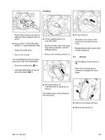
6.7 Piston - Remove the cylinder, b 6.5 The snap ring at the clutch side cannot be removed. If the piston pin is stuck, release it by tapping the end of the drift lightly 1 with a hammer. Hold the piston steady during this process to ensure that no jolts are transmitted to the connecting rod. - Remove the piston. 533RA125 TG - Inspect the piston rings and replace if necessary, b 6.8 : Push the assembly drift (1) 1108 893 4700, small diameter first, through the piston and small end (needle cage) and line up the piston. 4903RA087 TG : At the ignition side, use a suitable tool at the recess (arrow) to remove the hookless snap ring from the piston boss. 1 4903RA252 TG 1 2 : Pull out the needle cage (1), check it and replace if necessary, 1 b 14 533RA126 TG Installing 1 - Lubricate the piston pin (2) with oil. : Fit the piston pin (2) on the assembly drift (1) and slide it into the piston. 533RA121 TG : Push the assembly drift (1) 1108 893 4700 through the installed snap ring. 4903RA088 TG : Use the assembly drift (1) 1108 893 4700 to push the piston pin out of the piston. - Lubricate the needle cage with oil and push it into the connecting rod. 0001RA481 TG - Position the piston as shown so that the mark (arrow) points to the rear and the long crankshaft stub (1) is on the right. - Place the piston on the connecting rod. 2 1 : Remove the sleeve (1) from the installing tool (2) 5910 890 2212. 36 MS 311, MS 391
-
 1
1 -
2
-
3
-
4
-
5
-
6
-
7
-
8
-
9
-
10
-
11
-
12
-
13
-
14
-
15
-
16
-
17
-
18
-
19
-
20
-
21
-
22
-
23
-
24
-
25
-
26
-
27
-
28
-
29
-
30
-
31
-
 32
32 -
 33
33 -
 34
34 -
 35
35 -
 36
36 -
 37
37 -
 38
38 -
 39
39 -
 40
40 -
 41
41 -
 42
42 -
43
-
44
-
45
-
46
-
47
-
48
-
49
-
50
-
51
-
52
-
53
-
54
-
55
-
56
-
57
-
58
-
59
-
60
-
61
-
62
-
63
-
64
-
65
-
66
-
67
-
68
-
69
-
70
-
71
-
72
-
73
-
74
-
75
-
76
-
77
-
78
-
79
-
80
-
81
-
82
-
83
-
84
-
85
-
86
-
87
-
88
-
89
-
90
-
91
-
92
-
93
-
94
 |
 |
