Stihl MS 311 User Manual - Page 68
Valve, Installing
 |
View all Stihl MS 311 manuals
Add to My Manuals
Save this manual to your list of manuals |
Page 68 highlights
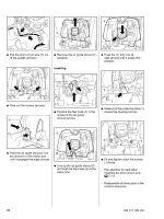
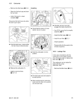
4903RA186 TG 1 2 2 11.4 Valve Installing A valve is installed in the tank wall to keep internal tank pressure equal to atmospheric pressure. The valve must be replaced if it is faulty. - Open the oil tank cap and drain the oil tank b 1. 4903RA184 TG - Place the oil pump (1) in position. : Fit and tighten down the screws (2) firmly. - Connect the oil suction hose to the oil pump. - Push the worm fully home. Check correct installed position. : Insert the valve in the housing bore (arrow). - Use a 6 mm drift to carefully drive in the new valve from outside - note installed depth. 4903RA185 TG : Use a 6 mm drift to carefully drive the valve out of its seat in the housing and into the oil tank. 1 219RA479 TG 4903RA270 TG : Fit the cover washer (1) so that the word TOP (arrow) faces outwards. - Check adjustment of oil pump and readjust if necessary - see instruction manual. 1 : Remove the old valve (1) from the oil tank. - Reassemble all other parts in the reverse sequence. 219RA476 TG : Installed depth of new valve: a = 1 mm +/- 0.1. - Reassemble all other parts in the reverse sequence. MS 311, MS 391 67
-
 1
1 -
2
-
3
-
4
-
5
-
6
-
7
-
8
-
9
-
10
-
11
-
12
-
13
-
14
-
15
-
16
-
17
-
18
-
19
-
20
-
21
-
22
-
23
-
24
-
25
-
26
-
27
-
28
-
29
-
30
-
31
-
32
-
33
-
34
-
35
-
36
-
37
-
38
-
39
-
40
-
41
-
42
-
43
-
44
-
45
-
46
-
47
-
48
-
49
-
50
-
51
-
52
-
53
-
54
-
55
-
56
-
57
-
58
-
59
-
60
-
61
-
62
-
 63
63 -
 64
64 -
 65
65 -
 66
66 -
 67
67 -
 68
68 -
 69
69 -
 70
70 -
 71
71 -
 72
72 -
 73
73 -
74
-
75
-
76
-
77
-
78
-
79
-
80
-
81
-
82
-
83
-
84
-
85
-
86
-
87
-
88
-
89
-
90
-
91
-
92
-
93
-
94
 |
 |
