Stihl MS 311 User Manual - Page 30
Vacuum Test, Pressure Test - 20 bar
 |
View all Stihl MS 311 manuals
Add to My Manuals
Save this manual to your list of manuals |
Page 30 highlights
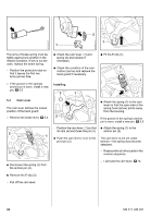
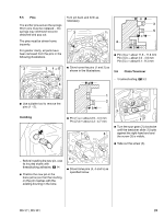
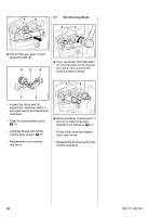
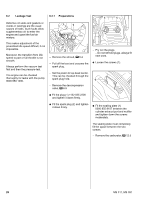
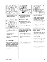
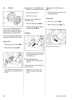
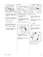
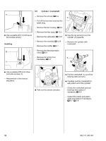
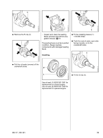
2 4 3 2 3 1 4903RA239 TG 4903RA238 TG 4903RA225 TG 1 2 1 : Check that the sleeve (1) and washer (2) are in place. 2 1 2 - Line up the flange (1) 1140 890 1200 and fit it over the studs : Fit the test flange (1) 1140 890 1200. 4903RA237 TG : Connect suction hose (1) of pump 0000 850 1300 to the nipple (arrow). : Push ring (2) to the left. : Operate the lever (3) until the pressure gauge (4) indicates a vacuum of 0.5 bar. If the vacuum reading remains constant, or rises to no more than 0.3 bar within 20 seconds, it can be assumed that the oil seals are in good condition. However, if the pressure continues to rise (reduced vacuum in the engine), the oil seals must be replaced, b 6.3. - After finishing the test, push the ring to the right to vent the pump. : Push ring (1) to the right. : Operate the lever (2) until the pressure gauge (3) indicates a pressure of 0.5 bar. If this pressure remains constant for at least 20 seconds, the engine housing is airtight. - If the pressure drops, the leak must be located and the faulty part replaced. To find the leak, coat the suspect area with oil and pressurize the engine housing again. Bubbles will appear if a leak exists. - After finishing the test, push the ring to the left to vent the pump - disconnect the hose. : Fit the nuts (2) and tighten them down firmly. 6.2.2 Vacuum Test Oil seals tend to fail when subjected to a vacuum, i.e. the sealing lip lifts away from the crankshaft during the piston's induction stroke because there is no internal counterpressure. A test can be carried out with pump 0000 850 1300 to detect this kind of fault. - Continue with pressure test, b 6.2.3 6.2.3 Pressure Test Carry out the same preparations as for the vacuum test, b 6.2.2 - Remove the flange. - Loosen the screws on the muffler and pull out the sealing plate. - Tighten down muffler screws firmly and fit new plugs. - Install the carburetor, b 12.5 - Reassemble all other parts in the reverse sequence. MS 311, MS 391 29
-
 1
1 -
2
-
3
-
4
-
5
-
6
-
7
-
8
-
9
-
10
-
11
-
12
-
13
-
14
-
15
-
16
-
17
-
18
-
19
-
20
-
21
-
22
-
23
-
24
-
 25
25 -
 26
26 -
 27
27 -
 28
28 -
 29
29 -
 30
30 -
 31
31 -
 32
32 -
 33
33 -
 34
34 -
 35
35 -
36
-
37
-
38
-
39
-
40
-
41
-
42
-
43
-
44
-
45
-
46
-
47
-
48
-
49
-
50
-
51
-
52
-
53
-
54
-
55
-
56
-
57
-
58
-
59
-
60
-
61
-
62
-
63
-
64
-
65
-
66
-
67
-
68
-
69
-
70
-
71
-
72
-
73
-
74
-
75
-
76
-
77
-
78
-
79
-
80
-
81
-
82
-
83
-
84
-
85
-
86
-
87
-
88
-
89
-
90
-
91
-
92
-
93
-
94
 |
 |
