Stihl MS 311 User Manual - Page 25
Cam Lever, Installing
 |
View all Stihl MS 311 manuals
Add to My Manuals
Save this manual to your list of manuals |
Page 25 highlights
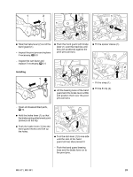
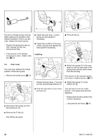
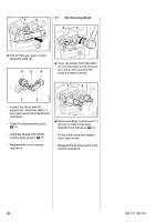
2 1 1 4903RA042 TG 4903RA040 TG 4903RA038 TG The turns of brake spring must be : Check the cam lever (1) and : Fit the E-clip (1). tightly against one another in the spring (2) and replace if relaxed condition. If this is not the necessary. case, replace the brake spring. : Check the condition of the cam 2 - Position the protective tube so contour (arrow) and replace the that it leaves the first two hand guard if necessary. turns (arrow) free. 1 - If the groove in the spring's anchor pin is worn, install a new pin, b 5.5 Installing 3 1 4903RA043 TG 5.4 Cam Lever The cam lever defines the locked position of the hand guard. - Remove the brake lever, b 5.3 2 1 3 2 - Position the cam lever (1) so that its cam (arrow) faces the pin (3). 4903RA041 TG : Attach the spring (1) to the cam lever so that the open side of the spring hook (arrow) points away from the housing. If the groove in the spring's anchor pin is worn, install a new pin, b 5.5 : Attach the spring (1) to the anchor pin (2). : Push the cam lever (1) on to the pivot pin (2). The cam lever is not yet under tension - the spring may become detached. - Reassemble all other parts in the reverse sequence. 4903RA039 TG : Disconnect the spring (1) from the anchor pin (2). : Remove the E-clip (3). - Lubricate the cam lever, b 14 - Pull off the cam lever. 24 MS 311, MS 391
-
 1
1 -
2
-
3
-
4
-
5
-
6
-
7
-
8
-
9
-
10
-
11
-
12
-
13
-
14
-
15
-
16
-
17
-
18
-
19
-
 20
20 -
 21
21 -
 22
22 -
 23
23 -
 24
24 -
 25
25 -
 26
26 -
 27
27 -
 28
28 -
 29
29 -
 30
30 -
31
-
32
-
33
-
34
-
35
-
36
-
37
-
38
-
39
-
40
-
41
-
42
-
43
-
44
-
45
-
46
-
47
-
48
-
49
-
50
-
51
-
52
-
53
-
54
-
55
-
56
-
57
-
58
-
59
-
60
-
61
-
62
-
63
-
64
-
65
-
66
-
67
-
68
-
69
-
70
-
71
-
72
-
73
-
74
-
75
-
76
-
77
-
78
-
79
-
80
-
81
-
82
-
83
-
84
-
85
-
86
-
87
-
88
-
89
-
90
-
91
-
92
-
93
-
94
 |
 |
