Stihl MS 311 User Manual - Page 84
Installing, Tank Vent, 10.1 Testing, Vacuum test
 |
View all Stihl MS 311 manuals
Add to My Manuals
Save this manual to your list of manuals |
Page 84 highlights
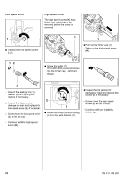
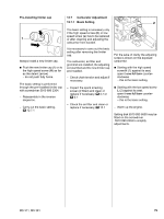
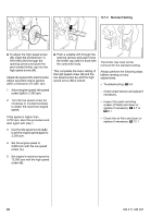
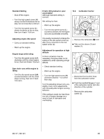
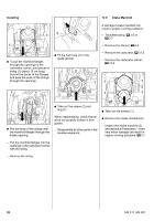
0001RA404 TG 0001RA407 TG : Inspect and clean the sealing faces (arrows), b 14 The sealing faces must be in perfect condition. Always replace components with damaged sealing faces. 12.10 Tank Vent 12.10.1 Testing If problems occur on the carburetor or the fuel supply system, also check and clean the tank vent and replace it if necessary. Check function by performing pressure and vacuum tests on the tank via the fuel hose. - Open the fuel tank cap and drain the fuel tank, b 1. - Close the tank cap. - Remove the carburetor, b 12.5 Vacuum test 2 1 : Push the ring (1) to the left and connect the pump (2) 0000 850 1300 to the nipple (arrow) - subject the fuel tank to a vacuum. Installing 1 1 2 1 1 Equalization of pressure takes place via the tank vent. There must be no buildup of vacuum in the fuel tank. - Clean the area around the tank 1 vent. - Always install a new fuel hose. 4903RA236 TG 0001RA406 TG : Position the manifold (2) on the cylinder. : Push the nipple (1) 0000 855 9200 into the fuel hose (arrow). - If necessary, install a new tank vent or fuel tank, b 12.10 or b 12.11.4 : Fit and tighten down the screws (1) firmly. - Install the carburetor carrier, b 12.8 - Reassemble all other parts in the reverse sequence. MS 311, MS 391 83
-
 1
1 -
2
-
3
-
4
-
5
-
6
-
7
-
8
-
9
-
10
-
11
-
12
-
13
-
14
-
15
-
16
-
17
-
18
-
19
-
20
-
21
-
22
-
23
-
24
-
25
-
26
-
27
-
28
-
29
-
30
-
31
-
32
-
33
-
34
-
35
-
36
-
37
-
38
-
39
-
40
-
41
-
42
-
43
-
44
-
45
-
46
-
47
-
48
-
49
-
50
-
51
-
52
-
53
-
54
-
55
-
56
-
57
-
58
-
59
-
60
-
61
-
62
-
63
-
64
-
65
-
66
-
67
-
68
-
69
-
70
-
71
-
72
-
73
-
74
-
75
-
76
-
77
-
78
-
 79
79 -
 80
80 -
 81
81 -
 82
82 -
 83
83 -
 84
84 -
 85
85 -
 86
86 -
 87
87 -
 88
88 -
 89
89 -
90
-
91
-
92
-
93
-
94
 |
 |
