Stihl MS 311 User Manual - Page 74
Installing, Inlet Needle
 |
View all Stihl MS 311 manuals
Add to My Manuals
Save this manual to your list of manuals |
Page 74 highlights
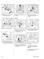
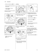
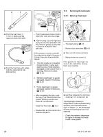
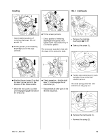
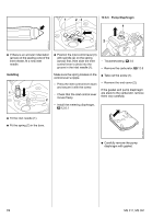
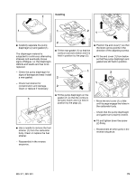
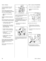
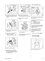
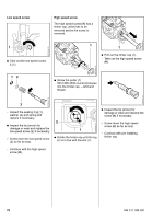
Installing 2 1 12.6.2 Inlet Needle 1 4903RA188 TG 4903RA190 TG 0001RA353 TG - Note installed positions of metering diaphragm (2) and gasket (1). : Fit the gasket (1) and metering diaphragm (2) on the pegs (arrows). : Fit the screws (arrows). - Check position of metering diaphragm and gasket, then tighten down the screws firmly in a crosswise pattern. The end cover must be in line with the edge of the carburetor body. - Remove the metering diaphragm, b 12.6.1 : Take out the screw (1). 21 2 1 1 0001RA361 TG 4903RA191 TG 4903RA189 TG : Position the end cover (1) so that the lever (arrow) points in the direction of the choke shutter. - Move the end cover (1) a little until the pegs engage the holes in the end cover. : Check operation - throttle shaft lever (1) must engage the air valve lever (2). - Reassemble all other parts in the reverse sequence. : Pull the inlet control lever (1) with spindle (2) out of the inlet needle's groove. The small spring under the inlet control lever may pop out. 1 2 0001RA362 TG : Remove the inlet needle (1). - Remove the spring (2). MS 311, MS 391 73
-
 1
1 -
2
-
3
-
4
-
5
-
6
-
7
-
8
-
9
-
10
-
11
-
12
-
13
-
14
-
15
-
16
-
17
-
18
-
19
-
20
-
21
-
22
-
23
-
24
-
25
-
26
-
27
-
28
-
29
-
30
-
31
-
32
-
33
-
34
-
35
-
36
-
37
-
38
-
39
-
40
-
41
-
42
-
43
-
44
-
45
-
46
-
47
-
48
-
49
-
50
-
51
-
52
-
53
-
54
-
55
-
56
-
57
-
58
-
59
-
60
-
61
-
62
-
63
-
64
-
65
-
66
-
67
-
68
-
 69
69 -
 70
70 -
 71
71 -
 72
72 -
 73
73 -
 74
74 -
 75
75 -
 76
76 -
 77
77 -
 78
78 -
 79
79 -
80
-
81
-
82
-
83
-
84
-
85
-
86
-
87
-
88
-
89
-
90
-
91
-
92
-
93
-
94
 |
 |
