Stihl MS 311 User Manual - Page 78
the carburetor
 |
View all Stihl MS 311 manuals
Add to My Manuals
Save this manual to your list of manuals |
Page 78 highlights
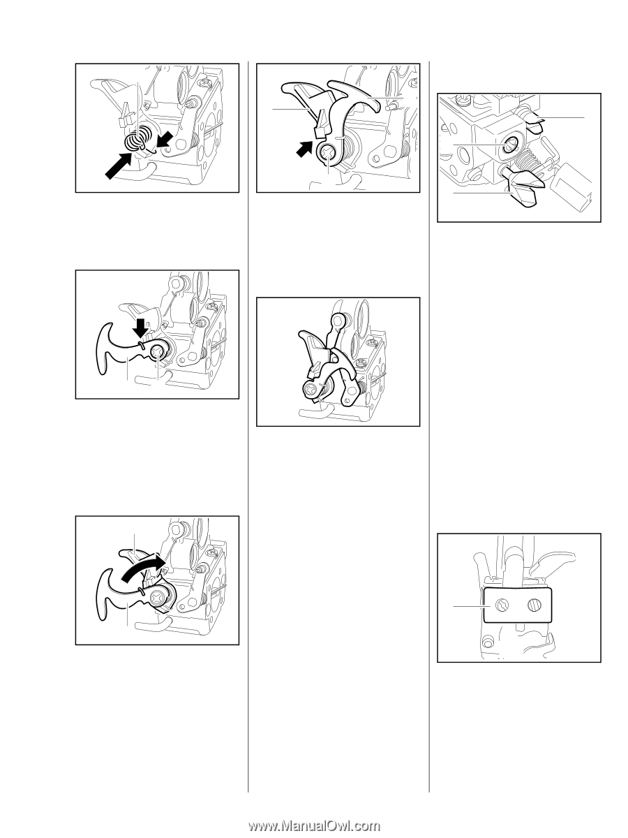
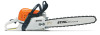
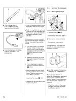
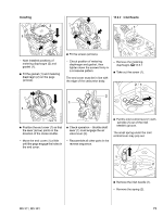
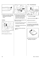
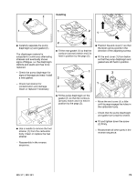
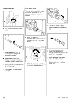
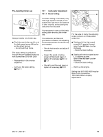
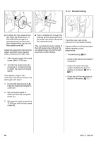
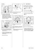
1 2 12.6.6 Adjusting Screws 1 2 1 4903RA199 TG 4903RA196 TG : Fit the torsion spring (1) so that its leg locates against the lever (arrow). 12 : Attach the torsion spring to the lever (arrow). : Fit the lever (1) and tighten the screw (2) moderately - the lever must still turn freely. 4903RA197 TG 3 : Hold lever (1) and lever (2) together against the stop (arrow). : Tighten down the screw (3) firmly. 3 Grommet has been removed for the sake of clarity. There are three adjusting screws on the carburetor: H = high speed screw (1) L = low speed screw (2) LA = idle speed screw (3) 0001RA382 TG If the carburetor cannot be adjusted properly, the problem may be the adjusting screws. 4903RA200 TG - Check operation. - Reassemble all other parts in the reverse sequence. The high speed screw H has a limiter cap, which has to be removed before the screw is removed. - Remove the carburetor, b 12.5 - See also carburetor troubleshooting, b 3.6 2 4903RA198 TG 0001RA383 TG 1 : Hold the lever (2) steady. : Rotate the lever (1) clockwise until it butts against the stop on lever (2) and engages the end of the throttle shaft. 1 : Pull off the grommet (1). MS 311, MS 391 77
-
 1
1 -
2
-
3
-
4
-
5
-
6
-
7
-
8
-
9
-
10
-
11
-
12
-
13
-
14
-
15
-
16
-
17
-
18
-
19
-
20
-
21
-
22
-
23
-
24
-
25
-
26
-
27
-
28
-
29
-
30
-
31
-
32
-
33
-
34
-
35
-
36
-
37
-
38
-
39
-
40
-
41
-
42
-
43
-
44
-
45
-
46
-
47
-
48
-
49
-
50
-
51
-
52
-
53
-
54
-
55
-
56
-
57
-
58
-
59
-
60
-
61
-
62
-
63
-
64
-
65
-
66
-
67
-
68
-
69
-
70
-
71
-
72
-
 73
73 -
 74
74 -
 75
75 -
 76
76 -
 77
77 -
 78
78 -
 79
79 -
 80
80 -
 81
81 -
 82
82 -
 83
83 -
84
-
85
-
86
-
87
-
88
-
89
-
90
-
91
-
92
-
93
-
94
 |
 |