Toshiba NB305-N411BL User Manual - Page 30
Underside, Battery safety lock, Speaker, Memory module slot, Battery release latch, Battery pack
 |
View all Toshiba NB305-N411BL manuals
Add to My Manuals
Save this manual to your list of manuals |
Page 30 highlights
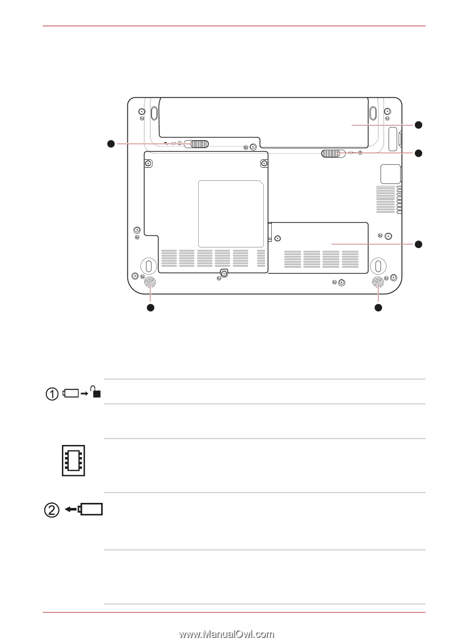
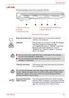
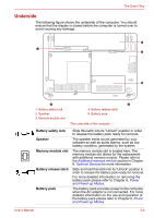
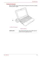
The Grand Tour Underside The following figure shows the underside of the computer. You should ensure that the display is closed before the computer is turned over to avoid causing any damage. 5 1 4 3 2 2 1. Battery safety lock 2. Speaker 3. Memory module slot 4. Battery release latch 5. Battery pack The underside of the computer Battery safety lock Speaker Memory module slot Battery release latch Battery pack Slide this latch into its "Unlock" position in order to release the battery pack ready for removal. The speaker emits sound generated by your software as well as audio alarms, such as low battery condition, generated by the system. The memory module slot is located here. The memory module slot allows for the replacement with additional memory module. Please refer to the Additional memory module section in Chapter 8, Optional Devices for more information. Slide and hold this latch into its "Unlock" position in order to release the battery pack ready for removal. For more detailed information on removing the battery pack please refer to Chapter 6, Power and Power-up Modes. The battery pack provides power to the computer when the AC adaptor is not connected. For more detailed information on the use and operation of the battery pack please refer to Chapter 6, Power and Power-up Modes. User's Manual 2-6
-
 1
1 -
2
-
3
-
4
-
5
-
6
-
7
-
8
-
9
-
10
-
11
-
12
-
13
-
14
-
15
-
16
-
17
-
18
-
19
-
20
-
21
-
22
-
23
-
24
-
 25
25 -
 26
26 -
 27
27 -
 28
28 -
 29
29 -
 30
30 -
 31
31 -
 32
32 -
 33
33 -
 34
34 -
 35
35 -
36
-
37
-
38
-
39
-
40
-
41
-
42
-
43
-
44
-
45
-
46
-
47
-
48
-
49
-
50
-
51
-
52
-
53
-
54
-
55
-
56
-
57
-
58
-
59
-
60
-
61
-
62
-
63
-
64
-
65
-
66
-
67
-
68
-
69
-
70
-
71
-
72
-
73
-
74
-
75
-
76
-
77
-
78
-
79
-
80
-
81
-
82
-
83
-
84
-
85
-
86
-
87
-
88
-
89
-
90
-
91
-
92
-
93
-
94
-
95
-
96
-
97
-
98
-
99
-
100
-
101
-
102
-
103
-
104
-
105
-
106
-
107
-
108
-
109
-
110
-
111
-
112
-
113
-
114
-
115
-
116
-
117
-
118
-
119
-
120
-
121
-
122
-
123
-
124
-
125
-
126
-
127
-
128
-
129
-
130
-
131
-
132
-
133
-
134
-
135
-
136
-
137
-
138
-
139
-
140
-
141
-
142
-
143
 |
 |