Toshiba Portege S100 PPS10C-LS101E Users Manual Canada; English - Page 50
Battery lock, Notches, Battery release, latch, Docking interface, Ultra Slim Bay, screw
 |
View all Toshiba Portege S100 PPS10C-LS101E manuals
Add to My Manuals
Save this manual to your list of manuals |
Page 50 highlights
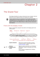
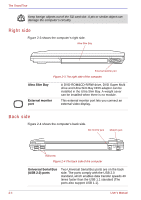
The Grand Tour Battery lock Battery pack Notches Battery release latch Docking interface Slide this lock to release the battery pack for removal. The battery pack powers the computer when the AC adaptor is not connected. For detailed information on the battery pack, refer to Chapter 6, Power and Power-Up Modes. Notches on the computer engage hooks on the Advanced Port Replicator III to hold the connection securely. Slide and hold this latch to release the battery pack for removal. For detailed information on removing the battery packs, refer to Chapter 6, Power and Power-Up Modes. This port enables connection of an optional Advanced Port Replicator III described in Chapter 8, Optional Devices. Keep foreign objects out of the docking interface port. A pin or similar object can damage the computer's circuitry. A plastic shutter protects the connector. Ultra Slim Bay Ultra Slim Bay lock See the Right side section in this chapter for details. Slide the lock to release or secure the Ultra Slim Bay ejector. Be sure to lock the Ultra Slim Bay lock before you transport or carry the computer. Ultra Slim Bay lock One screw secures the Ultra Slim Bay lock. screw 2-6 User's Manual
-
 1
1 -
2
-
3
-
4
-
5
-
6
-
7
-
8
-
9
-
10
-
11
-
12
-
13
-
14
-
15
-
16
-
17
-
18
-
19
-
20
-
21
-
22
-
23
-
24
-
25
-
26
-
27
-
28
-
29
-
30
-
31
-
32
-
33
-
34
-
35
-
36
-
37
-
38
-
39
-
40
-
41
-
42
-
43
-
44
-
 45
45 -
 46
46 -
 47
47 -
 48
48 -
 49
49 -
 50
50 -
 51
51 -
 52
52 -
 53
53 -
 54
54 -
 55
55 -
56
-
57
-
58
-
59
-
60
-
61
-
62
-
63
-
64
-
65
-
66
-
67
-
68
-
69
-
70
-
71
-
72
-
73
-
74
-
75
-
76
-
77
-
78
-
79
-
80
-
81
-
82
-
83
-
84
-
85
-
86
-
87
-
88
-
89
-
90
-
91
-
92
-
93
-
94
-
95
-
96
-
97
-
98
-
99
-
100
-
101
-
102
-
103
-
104
-
105
-
106
-
107
-
108
-
109
-
110
-
111
-
112
-
113
-
114
-
115
-
116
-
117
-
118
-
119
-
120
-
121
-
122
-
123
-
124
-
125
-
126
-
127
-
128
-
129
-
130
-
131
-
132
-
133
-
134
-
135
-
136
-
137
-
138
-
139
-
140
-
141
-
142
-
143
-
144
-
145
-
146
-
147
-
148
-
149
-
150
-
151
-
152
-
153
-
154
-
155
-
156
-
157
-
158
-
159
-
160
-
161
-
162
-
163
-
164
-
165
-
166
-
167
-
168
-
169
-
170
-
171
-
172
-
173
-
174
-
175
-
176
-
177
-
178
-
179
-
180
-
181
-
182
-
183
-
184
-
185
-
186
-
187
-
188
-
189
-
190
-
191
-
192
-
193
-
194
-
195
-
196
-
197
-
198
-
199
-
200
-
201
-
202
-
203
-
204
-
205
-
206
-
207
-
208
-
209
-
210
-
211
-
212
-
213
-
214
-
215
-
216
-
217
-
218
-
219
-
220
-
221
-
222
-
223
-
224
-
225
-
226
-
227
-
228
-
229
-
230
-
231
-
232
-
233
-
234
-
235
-
236
-
237
-
238
-
239
-
240
-
241
-
242
-
243
-
244
-
245
-
246
-
247
-
248
-
249
-
250
-
251
-
252
 |
 |
