3Com 3C17304 Getting Started Guide - Page 23
Placing Units On Top of Each Other, Stacking Units, m 328 ft can be used for stacking. - 4228g factory defaults
 |
View all 3Com 3C17304 manuals
Add to My Manuals
Save this manual to your list of manuals |
Page 23 highlights
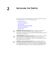
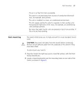
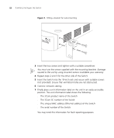
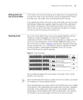
Placing Units On Top of Each Other 23 Placing Units On Top of Each Other If the Switch units are free-standing, up to eight units can be placed one on top of the other. If you are mixing a variety of SuperStack® 3 Switch and Hub units, the smaller units must be positioned at the top. If you are placing Switch units one on top of the other, you must use the self-adhesive rubber pads supplied. Apply the pads to the underside of each Switch, sticking one in the marked area at each corner. Place the Switch units on top of each other, ensuring that the pads of the upper unit line up with the recesses of the lower unit. Stacking Units Up to four Switch 4200 Series units can be stacked together and then treated as a single manageable unit with one IP address. Any combination of Switch 4200 Series units is allowed in a single stack. The units are connected together via the 10/100/1000BASE-T ports on the front of the unit as shown in Figure 6. Starting from the base of the stack, the port marked with 'up' is connected to the port marked with 'down' on the unit above. Cable lengths of between 14 cm (5.5 in) and 100 m (328 ft) can be used for stacking. Figure 6 Stacking example 1 25 2 26 3 27 4 28 5 29 6 30 7 31 8 32 9 33 10 34 11 35 12 36 13 37 14 38 15 39 16 40 17 41 18 42 19 43 3C17302 Superstack 3 Switch 4250T 20 44 21 45 22 46 23 47 24 48 Power/ Self Test 1 Up Down 2 3 Alert 4 Unit 49 50 1 13 2 14 3 15 4 16 5 17 6 18 7 19 8 20 9 21 10 22 11 23 12 24 Power/ Self Test 1 25 / Up 26 / Down 2 3 Alert 4 Unit 27 27 28 3C17304 Superstack 3 Switch 4228G 28 1 13 2 14 3 15 4 16 5 17 6 18 7 19 8 20 9 21 10 22 11 23 12 24 Power/ Self Test 1 25 / Up 26 / Down 2 3 Alert 4 Unit 27 27 28 3C17304 Superstack 3 Switch 4228G 28 1 13 2 14 3 15 4 16 5 17 6 18 7 19 8 20 9 21 10 22 11 23 12 24 Power/ Self Test 1 25 / Up 26 / Down 2 3 Alert 4 Unit 3C17300 Superstack 3 Switch 4226T The unit LEDs will display the unit number in the stack, from 1 at the bottom to 4 at the top. 3Com recommends that when you add a new unit to a stack, you should first initialize it to factory default settings Stack renumbering occurs when another Switch 4200 Series unit is added to the bottom of an established stack except when the stack is already 4 units high. In this instance the 'down' port on the bottom unit of the existing stack will be disabled and its LED will flash green. You will then not be able to use that port again until the link is lost on that port.
-
 1
1 -
2
-
3
-
4
-
5
-
6
-
7
-
8
-
9
-
10
-
11
-
12
-
13
-
14
-
15
-
16
-
17
-
 18
18 -
 19
19 -
 20
20 -
 21
21 -
 22
22 -
 23
23 -
 24
24 -
 25
25 -
 26
26 -
 27
27 -
 28
28 -
29
-
30
-
31
-
32
-
33
-
34
-
35
-
36
-
37
-
38
-
39
-
40
-
41
-
42
-
43
-
44
-
45
-
46
-
47
-
48
-
49
-
50
-
51
-
52
-
53
-
54
-
55
-
56
-
57
-
58
-
59
-
60
-
61
-
62
-
63
-
64
-
65
-
66
-
67
-
68
-
69
-
70
-
71
-
72
-
73
-
74
-
75
-
76
-
77
-
78
-
79
-
80
-
81
-
82
-
83
-
84
 |
 |