3Com 3C17304 Getting Started Guide - Page 24
The Power-up Sequence, Powering-up the Switch 4200 Series, Checking for Correct Operation of LEDs
 |
View all 3Com 3C17304 manuals
Add to My Manuals
Save this manual to your list of manuals |
Page 24 highlights
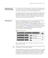
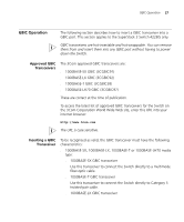
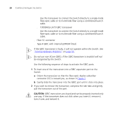
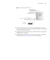
24 CHAPTER 2: INSTALLING THE SWITCH When another Switch 4200 Series unit is added to the top of an established stack, no stack renumbering occurs. If however the unit being added takes the stack height above 4 then the 'up' port on the top unit of the existing stack will be disabled and its LED will flash green. You will then not be able to use that port again until the link is lost on that port. When removing a Switch from a stack, note the following: ■ Removing a Switch 4200 Series unit from the bottom of an existing stack will cause the remaining stack to renumber. ■ Removing a Switch 4200 Series unit from the middle of an existing stack will cause the other Switches in the stack to divide into two stacks. Units below the unit removed will not renumber, units above will renumber. ■ Removing a Switch 4200 Series unit from the top of an existing stack will have no effect on the remaining stack. If you are having problems, refer to "Solving Stack Formation Problems" on page 56. The Power-up Sequence The following sections describe how to get your Switch 4200 Series powered-up and ready for operation. Powering-up the Use the following sequence of steps to power-up the Switch. Switch 4200 Series 1 Plug the power cord into the power socket at the rear of the Switch. 2 Plug the other end of the power cord into your power outlet. The Switch powers-up and runs through its Power On Self Test (POST), which takes approximately 10 seconds. Checking for Correct Operation of LEDs During the Power On Self Test, all ports on the Switch are disabled and the LEDs light in a set sequence. When the POST has completed, check the Power On Self Test LED to make sure that your Switch is operating correctly. Table 6 shows possible colors for the LED.
-
 1
1 -
2
-
3
-
4
-
5
-
6
-
7
-
8
-
9
-
10
-
11
-
12
-
13
-
14
-
15
-
16
-
17
-
18
-
 19
19 -
 20
20 -
 21
21 -
 22
22 -
 23
23 -
 24
24 -
 25
25 -
 26
26 -
 27
27 -
 28
28 -
 29
29 -
30
-
31
-
32
-
33
-
34
-
35
-
36
-
37
-
38
-
39
-
40
-
41
-
42
-
43
-
44
-
45
-
46
-
47
-
48
-
49
-
50
-
51
-
52
-
53
-
54
-
55
-
56
-
57
-
58
-
59
-
60
-
61
-
62
-
63
-
64
-
65
-
66
-
67
-
68
-
69
-
70
-
71
-
72
-
73
-
74
-
75
-
76
-
77
-
78
-
79
-
80
-
81
-
82
-
83
-
84
 |
 |