Brother International LK3-B432E MKII Instruction Manual - English - Page 13
INSTALLATION, 3-1 . Power table
 |
View all Brother International LK3-B432E MKII manuals
Add to My Manuals
Save this manual to your list of manuals |
Page 13 highlights
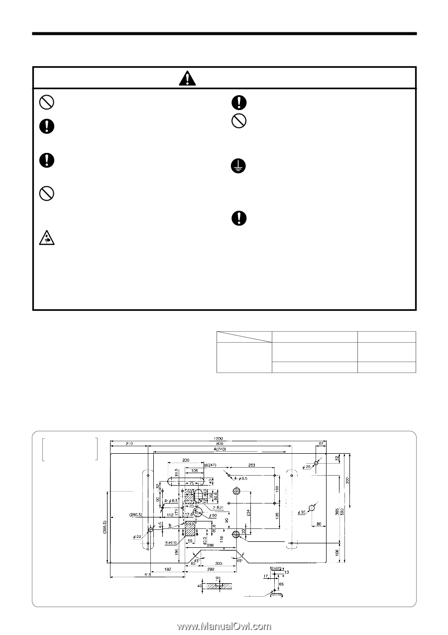
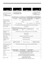
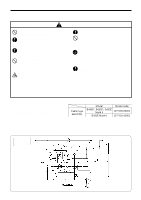
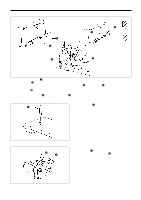
3. INSTALLATION 3. INSTALLATION CAUTION Machine installation should only be carried out by a qualified technician. Contact your Brother dealer or a qualified electrician for any electrical work that may need to be done. The sewing machine head weighs more than 47 kg. The installation should be carried out by two or more people. Do not connect the power cord until installation is complete, otherwise the machine may operate if the foot switch is depressed by mistake, which could result in injury. Hold the machine head with both hands when tilting it back or returning it to its original position. Furthermore, after tilting back the machine head, do not push the face plate side or the pulley side from above, as this could cause the machine head to topple over, which may result in personal injury or damage to the machine. All cords should be secured at least 25 mm away from any moving parts. Furthermore, do not excessively bend the cable or secure it too firmly staples, otherwise there is the danger that fire or electric shocks could occur. Be sure to connect the ground. If the ground connection is not secure, you run the risk of receiving a serious electric shock, and problems with correct operation may also occur. Install the belt covers to the machine head and motor. 3-1 . Power table • Use the power table which has been specially designed for each sewing machines. * If using a commercially-available table, process it as shown in the illustration below. Table/ legs assembly Model Model code B430E-, B432E-, B433E Mark II 127-V30-00001 B431E Mark II 127-V31-00001 NOTE: The thickness of the table should be at least 40 mm, and it should be strong enough to bear the weight and vibration of the sewing machine. If the distance A between the insides of the legs is less than 740 mm, move the control box installation position closer to the motor (B = 247 mm). Check that the control box is at least 10 mm away from the leg. If the control box and leg are touching, it could cause the sewing machine to operate incorrectly. LK3-B430E Mark II LK3-B432E Mark II LK3-B433E Mark II Motor Control Box Operation panel cord hole Counterbore depth 23 2-ø3 Section A-A depth 5 b 7 LK3-B430E-, B431E-, B432E-, B433E- Mark II
-
 1
1 -
2
-
3
-
4
-
5
-
6
-
7
-
 8
8 -
 9
9 -
 10
10 -
 11
11 -
 12
12 -
 13
13 -
 14
14 -
 15
15 -
 16
16 -
 17
17 -
 18
18 -
19
-
20
-
21
-
22
-
23
-
24
-
25
-
26
-
27
-
28
-
29
-
30
-
31
-
32
-
33
-
34
-
35
-
36
-
37
-
38
-
39
-
40
-
41
-
42
-
43
-
44
-
45
-
46
-
47
-
48
-
49
-
50
-
51
-
52
-
53
-
54
-
55
-
56
-
57
-
58
-
59
-
60
-
61
-
62
-
63
-
64
-
65
-
66
-
67
-
68
-
69
-
70
-
71
-
72
-
73
 |
 |