Brother International LK3-B432E MKII Instruction Manual - English - Page 18
. Installing the machine head, 3-9 . Installing the head rest
 |
View all Brother International LK3-B432E MKII manuals
Add to My Manuals
Save this manual to your list of manuals |
Page 18 highlights
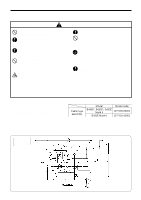
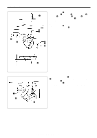
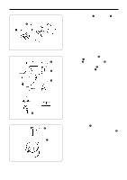
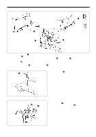
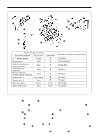
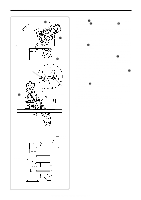
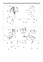
3-8 . Installing the machine head 3. INSTALLATION w q r t y u 66 17 13 e 1. Insert the head hinges q into the machine head so that they are parallel, and then secure them with the two set screws w. 2. Place the machine head gently on top of the rubber cushions e and cushions r. NOTE: Pull the cords t out as shown in the illustration above in order to prevent them from being clamped by the machine head. 3. Install the hinge presser y with the two screws u. 3-9 . Installing the head rest q Tap the head rest q into the table hole. NOTE: Tap the head rest securely into the table hole. 3-10 .Installing the liquid cooling tank, optional w q 1. Remove the rubber plug, and then push the liquid cooling tank q. 2. Tighten it with the set screw w. LK3-B430E-, B431E-, B432E-, B433E- Mark II 12
-
 1
1 -
2
-
3
-
4
-
5
-
6
-
7
-
8
-
9
-
10
-
11
-
12
-
 13
13 -
 14
14 -
 15
15 -
 16
16 -
 17
17 -
 18
18 -
 19
19 -
 20
20 -
 21
21 -
 22
22 -
 23
23 -
24
-
25
-
26
-
27
-
28
-
29
-
30
-
31
-
32
-
33
-
34
-
35
-
36
-
37
-
38
-
39
-
40
-
41
-
42
-
43
-
44
-
45
-
46
-
47
-
48
-
49
-
50
-
51
-
52
-
53
-
54
-
55
-
56
-
57
-
58
-
59
-
60
-
61
-
62
-
63
-
64
-
65
-
66
-
67
-
68
-
69
-
70
-
71
-
72
-
73
 |
 |
