Brother International LK3-B432E MKII Instruction Manual - English - Page 22
. Installing the belt cover, 3-16. Installing the foot switch, spring washer
 |
View all Brother International LK3-B432E MKII manuals
Add to My Manuals
Save this manual to your list of manuals |
Page 22 highlights
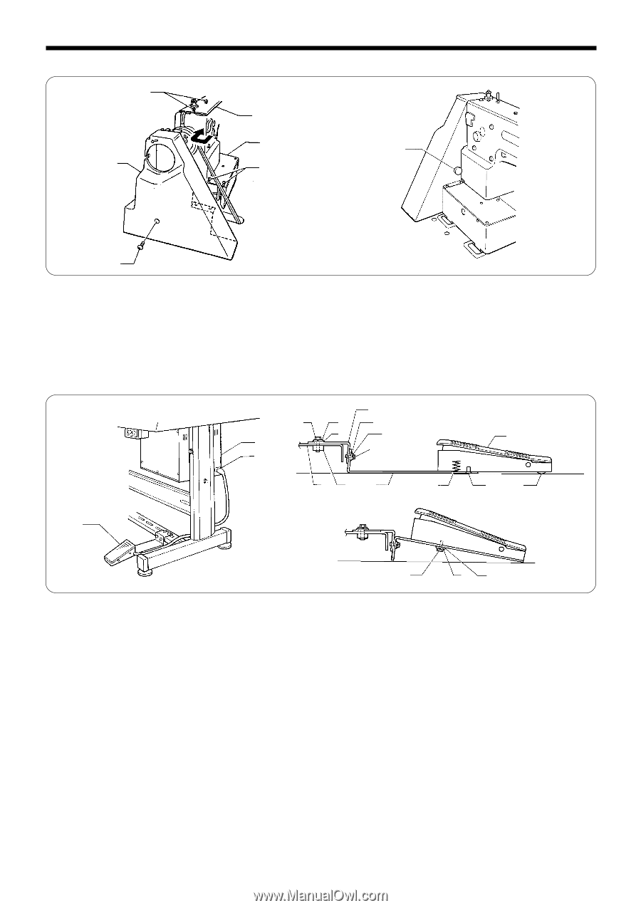
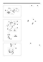
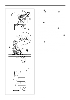
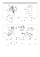
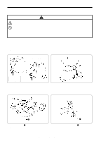
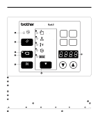
3-15 . Installing the belt cover w q e t r 3. INSTALLATION u y 1. Loosen the two screws w of the upper cover q and the two screws r of bed cover Le. 2. Insert the belt cover t in the direction of the arrow, and then secure it with the two screws w, the two screws r and the screw y. * When tilting back the machine head, loosen the screws w and r, remove the screw y and then remove the belt cover t first. 3. Attach the rubber plug u to the belt cover. 3-16. Installing the foot switch [A] y q w r u !1 i !0 o !2 t !3 !6 e !4 !5 [B] e !7 !8 !9 1. Insert the connector of the foot switch e into the connector w of the control box q. 2. Install the foot switch e to the work table leg !2 with foot switch support plate A r, foot switch support plate C t, the bolt y, spring washer u, flat washer i, bolt o, spring washer !0 and flat washer !1 as shown in Figure A. ♦If foot switch support plate B !3 is used in a back-to-front position, it can be used as shown in Figure. B. 1. Remove the screw !4 and rubber plug !5. * Note that the spring !6 will come out when the screw !4 is removed. 2. Turn foot switch support plate B !3 back to front, and then install it with the bolt !7, spring washer !8 and flat washer !9 as shown in Figure. B. NOTE: If using the foot switch without installing it to the work table leg, move the foot switch at least 10 mm away from the leg. If the foot switch is not fully in contact with the work table leg when the foot switch is used, for example, if it is just hooked loosely onto the work table leg, it may cause the sewing machine to operate incorrectly. If using the optional two-pedal foot switch, change the setting of DIP switch A on the oreration panel while referring to "Setting the presser mode" on page 44. LK3-B430E-, B431E-, B432E-, B433E- Mark II 16
-
 1
1 -
2
-
3
-
4
-
5
-
6
-
7
-
8
-
9
-
10
-
11
-
12
-
13
-
14
-
15
-
16
-
 17
17 -
 18
18 -
 19
19 -
 20
20 -
 21
21 -
 22
22 -
 23
23 -
 24
24 -
 25
25 -
 26
26 -
 27
27 -
28
-
29
-
30
-
31
-
32
-
33
-
34
-
35
-
36
-
37
-
38
-
39
-
40
-
41
-
42
-
43
-
44
-
45
-
46
-
47
-
48
-
49
-
50
-
51
-
52
-
53
-
54
-
55
-
56
-
57
-
58
-
59
-
60
-
61
-
62
-
63
-
64
-
65
-
66
-
67
-
68
-
69
-
70
-
71
-
72
-
73
 |
 |