Brother International LK3-B432E MKII Instruction Manual - English - Page 19
. Installing the operation panel, 3-12 . Connecting the ground wire
 |
View all Brother International LK3-B432E MKII manuals
Add to My Manuals
Save this manual to your list of manuals |
Page 19 highlights
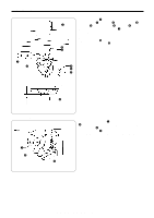
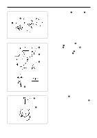
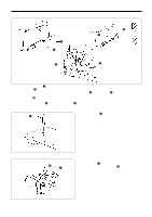
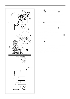
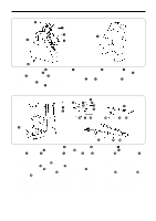
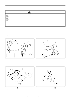
3. INSTALLATION 3-11 . Installing the operation panel The operation panel can be installed to either the top or bottom of the work table. Top of work table e Bottom of work table q r q r w e t w Table t Table 1. Install the rear frame q to the work table (top or bottom) with the four wood screws w. 2. Install the front frame e to the rear frame q with the four screws r. * The vertical orientation of the front frame e is the same whether it is installed to the top or the bottom of the work table. 3. Insert the connector cord t into the control box through the hole at the side of the box. Refer to "3-13. Connecting the cords" for details on connecting the cord. 4. Secure the connector cord t with the staples (in three places). 3-12 . Connecting the ground wire CAUTION Be sure to connect the ground. If the ground connection is not secure, you run the risk of receiving a serious electric shock, and problems with correct operation may also occur. Red White Black Yellow/Green Connect to the power switch. However, the black wire is insulated to the inside of the box and is not used. Connect to ground 13 LK3-B430E-, B431E-, B432E-, B433E- Mark II
-
 1
1 -
2
-
3
-
4
-
5
-
6
-
7
-
8
-
9
-
10
-
11
-
12
-
13
-
 14
14 -
 15
15 -
 16
16 -
 17
17 -
 18
18 -
 19
19 -
 20
20 -
 21
21 -
 22
22 -
 23
23 -
 24
24 -
25
-
26
-
27
-
28
-
29
-
30
-
31
-
32
-
33
-
34
-
35
-
36
-
37
-
38
-
39
-
40
-
41
-
42
-
43
-
44
-
45
-
46
-
47
-
48
-
49
-
50
-
51
-
52
-
53
-
54
-
55
-
56
-
57
-
58
-
59
-
60
-
61
-
62
-
63
-
64
-
65
-
66
-
67
-
68
-
69
-
70
-
71
-
72
-
73
 |
 |
